Building a controllable dice grid

Hello,

I am building a grid made of 20 x 20 dices, each 20x20x20 mm. I want to be able to lower and lift each dice by 20 mm, using some kind of actuators beneath the matrix with each 20mm stroke.

Each actuator should have a power of about 20 Newton.
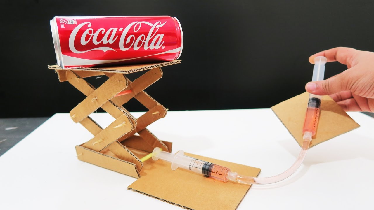
I am looking for the best solution for the "actuators" I could be a grid of controlled pneumatic cylinders, controlling electric valves, it could be electromagnets, it could be linear actuators with spindles. But as you can see, with 400 of these it should be a possibly cheapest solution. Does anyone have ideas, wich "actuator" could be an innovative an cheap way to achieve that?

Regards,

Paul

Interesting project that brings up some questions.

  1. What is the die made of? Since they obviously are pressing against each other, are you lubricating them so they will easily slide?
  2. What speed do they need to move?
  3. How will you know they have moved 20mm and how will you know they have lowered by 20mm?
  4. Is noise a concern?
  5. Are you using gravity to lower the die, since some of your suggestions are only one way movements, ie. electromagnets.

Die - singular
Dice - plural

Algebra based Physics course?

You can use a single actuator controlling its XY position with a couple of stepping motors and worm screws.

Hi, thanks for your reply an very good questions.

  • they are made from POM, so they have little friction, they will not be lubricated
  • there is no need for fast speed, it could be 20 mm in 1 minute.
  • they will have a moving freedom of exactly 20 mm, so the actuator does not have to be precise
  • noise does not matter
  • gravity could be used to lower them, I could also add weight in case its necessary.

Good idea, so that would definitely be the cheapest way. But with 400 Dice, this would also take a while. But I will consider it, thanks!

Can you show us a picture of a prototype device, say, 9X9 dice?

What is your parts budget? We have no idea what you consider "cheap."

You could probably get some ideas by looking at how Braille letters work, or this: Shape Memory Alloy Wire | Explore Jameco Electronics

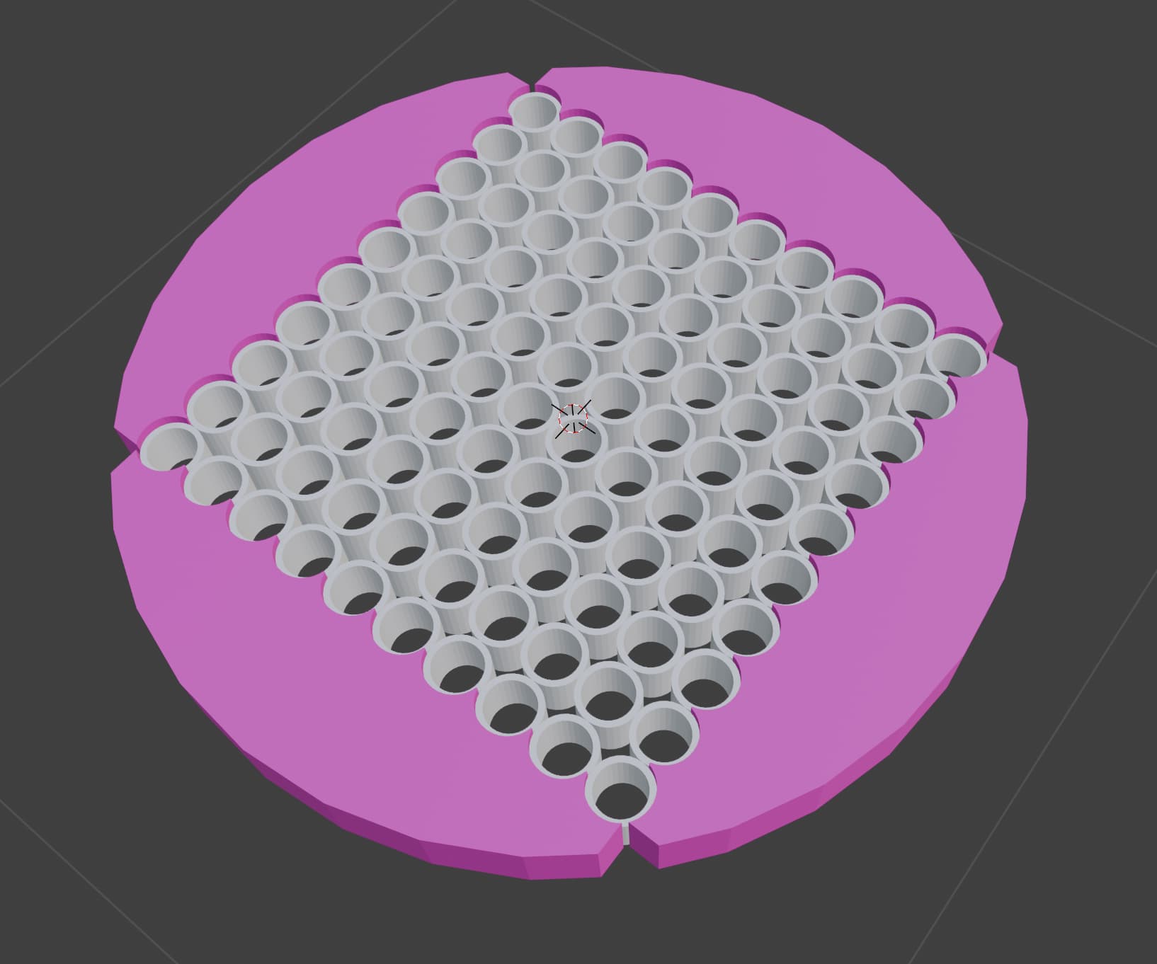
Here is a picture of a version with tubes instead of cubes. I guess, from the "challenge" described here, cubes or tubes should not make a big difference. But I hope this picture helps understanding what I want to achieve :slight_smile:

(The reason I have tubes here, is that for my prototype, tubes will be the cheapest test material)

Thanks! that is very interesting!

my Budget for just the "actuators" would be roughly 400 € for 400 actuators, 1€ per piece.

Ok, and what goes into the tube? And do you have a prototype to work with. So far you are designing the end result before you get the mechanical part worked out.

I guess we need more info about your project: what you are trying to accomplish here and where the requirement came from.

What is "a while"? Do you have a time constraint? Will you move several pieces simultaneously? How do you determine the sequence in which they should move?

Newton is a unit of force, not power.

I can't imagine any world in which this would hold true.

[edit]
OK. So if you exchange labor cost for parts cost it might be doable, but I'm not sure. What I have in mind are the ultra-cheap DC motors Amazon.com: NW 50pcs Coreless Motor 4x12mm DC 3.7V 69000RPM High Speed Model Aircraft Motor Strong Magnetic Motor for DIY Science Project : Toys & Games with an epoxied-on low-pitch screw and nut to make a cheap actuator. That might be possible at your target cost if you don't care about the labor time.

My thought here is a straight (not tapered) screw like a self-tapping sheet metal screw and a small piece of plastic to serve as the lead nut. In theory it would work, but I have no idea for how long :slight_smile:

Alternately, you could 3D print leadscrews and nuts.

1 Like

Not according to this:-

Even better: 1.5g servo, micro digital servo, linear servo, left and right pair of suitable fixed wings for Mier drones - AliExpress 26

My life has been a lice. : )

1 Like

That's the way English roles :wink:

The Tube will stay empty. The Whole construction is used to lift leight weight objects with a shape represented by the pipes that move. For example: If a ring would be lifted by the pipes or cubes, the pipes or cubes underneath that ring would go up 20 mm.

I do not have a prototype yet, I started of with visualizing the project in Blender.

Its less an issue of feasibility. I am just looking for the cheapest way to achieve it.

Thanks so far to all for the help and brain power!

I would like to move all pieces simultaneously, but if its too expensive, they could also lift the object in a sequenced order. But I would prefer it to be simultaneously.

If in a sequence, there is no need for a predefined order.

I get the "Newton"-mistake, sorry for that. I also mistyped: It should have been 200 Gram, not 2 kg each, sorry for that.

I would definitely trade labour time for part costs. Using cheap motors and screws is definitely a good idea I will follow up on. Thanks!