Burn bootloader atmega328p on a pcb board using usbasp programmer in Arduino IDE

Hi all! I had a pcb with an atmega328p on it. The pcb also has a 6-pin header for connecting to the computer using an usbasp programmer. However when I try to burn bootloader in Arduino IDE something went wrong. (I referred to the tutorial How to load Arduino bootloader into ATMEL microcontroller ATMEGA328P).

Error reported as follows:
"C:\Users\86130\AppData\Local\Arduino15\packages\MiniCore\tools\avrdude\7.2-arduino.1/bin/avrdude" "-CC:\Users\86130\AppData\Local\Arduino15\packages\MiniCore\hardware\avr\3.0.0/avrdude.conf" -v -patmega328 -cusbasp -e -Ulock:w:0xff:m -Uefuse:w:0b11111101:m -Uhfuse:w:0xd7:m -Ulfuse:w:0b11110111:m

avrdude: Version 7.2-arduino.1
Copyright the AVRDUDE authors;
see https://github.com/avrdudes/avrdude/blob/main/AUTHORS

     System wide configuration file is C:\Users\86130\AppData\Local\Arduino15\packages\MiniCore\hardware\avr\3.0.0\avrdude.conf

     Using Port                    : usb
     Using Programmer              : usbasp
     AVR Part                      : ATmega328
     Chip Erase delay              : 9000 us
     PAGEL                         : PD7
     BS2                           : PC2
     RESET disposition             : possible i/o
     RETRY pulse                   : SCK
     Serial program mode           : yes
     Parallel program mode         : yes
     Timeout                       : 200
     StabDelay                     : 100
     CmdexeDelay                   : 25
     SyncLoops                     : 32
     PollIndex                     : 3
     PollValue                     : 0x53
     Memory Detail                 :

                                       Block Poll               Page                       Polled
       Memory Type Alias    Mode Delay Size  Indx Paged  Size   Size #Pages MinW  MaxW   ReadBack
       ----------- -------- ---- ----- ----- ---- ------ ------ ---- ------ ----- ----- ---------
       eeprom                 65    20     4    0 no       1024    4      0  3600  3600 0x00 0x00
       flash                  65    10   128    0 yes     32768  128    256  4500  4500 0x00 0x00
       lfuse                   0     0     0    0 no          1    1      0  4500  4500 0x00 0x00
       hfuse                   0     0     0    0 no          1    1      0  4500  4500 0x00 0x00
       efuse                   0     0     0    0 no          1    1      0  4500  4500 0x00 0x00
       lock                    0     0     0    0 no          1    1      0  4500  4500 0x00 0x00
       signature               0     0     0    0 no          3    1      0     0     0 0x00 0x00
       calibration             0     0     0    0 no          1    1      0     0     0 0x00 0x00

     Programmer Type : usbasp
     Description     : USBasp ISP and TPI programmer

avrdude: auto set sck period (because given equals null)
avrdude usbasp_spi_program_enable() error: program enable: target does not answer (0x01)
avrdude main() error: initialization failed, rc=-1
- double check the connections and try again
- use -B to set lower the bit clock frequency, e.g. -B 125kHz
- use -F to override this check

avrdude done. Thank you.

Failed chip erase: uploading error: exit status 1

Does anyone have idea where I went wrong?

Post the schematic of your PCB. Maybe some other components are connected to pins that the programmer needs.

Or your Atmega328 has it's fuses programmed for a crystal, while there is no crystal on your board.


Hello, this is my schematic.

The numbering systems in use on your ISP header could cause some confusion. If what is
actually on the board does not match the conventional layout then ensure you connect the programmer appropriately.

Thanks! When I connect isp header to the programmer I refer to the pcb file (which is different from my schematic and I don't know why). But even if I connect them one to one it still do not work (I used jump wires for connection).

The normal layout of the ISP header is designed so that, if you accidentally reverse the connector, no damage is done. Hopefully, you discovered the error in time to avoid say a complete polarity reversal which may have caused permanent damage to the MCU chip.

The unexpected layout on the PCB is probably due to the internal pad numbering on that 3x2 pin header component you selected for the ISP header which may differ from that on the symbol used in the schematic. There is, incidentally, yet another numbering system where the pin pairs 1 and 2 are directly opposite each other as are the pairs 3 and 4 and the pairs 5 and 6.

The ISP header your schematic looks identical to mine (which I copied from my Nano V3).
The header on your PCB seems odd indeed.
I also see a crystal, so unless the copper traces to the crystal are very long I see no hardware anomalies in your schematic.

yes it's reallly weird

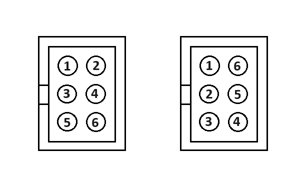
There seems to be two different numbering systems for the connector used for the ICSP connector:
Pin Numbers
I think your problem is that you are somehow mixing the two systems.

It could be that the part that you used out of the library wasn't numbered in the way you thought it was and you allocated the connections using the other numbering system.

the one on the left is correct, the one on the right is wrong.

....and that is the one that appears on the schematic in post #3.

Important only is that the numbering system on the schematic symbol matches that of chosen PCB component in order to get the board correct. There is a variety of possible schematic symbols in Kicad :

Definitly. That's why it pays reading the docs. In this case Figure 1-2.:

Hi guys, I tried another way to do this which is use a uno board to program the atmega328p and it worked! Appriciate for your help!

This topic was automatically closed 180 days after the last reply. New replies are no longer allowed.