I made sure to select "Arduino Leonardo" from the Toosl > Board menu, then select USBtinyISP from the Tools > Programmer menu. I hit the Tools > Burn bootloader option and let it go. It took a minute, but I eventually got a message saying "Done burning bootloader."
So I disconnected the USBtinyISP and plugged in my board via a USB cord. Windows does not make any noises, and the Device Manager shows nothing new. I see no new COM ports under the Tools > Serial Port menu. Did I do something wrong?
How do I upload new sketches my board? Do I have to use the USBtinyISP every time, or can I use the USB port?
What in the world...I have a weird gremlin now, not sure how to fix.
I do not have an oscilloscope, but I do have a basic multimeter with the beeping circuit tester.
When the board is disconnected, the board checks out just fine. I use my circuit tester to check every ground connection and make sure that nothing is connected that shouldn't be.
When I plug the board in, I check the same connections again and it seems that the ground and +5V lines are connected! This behavior persists for a little while after the board is disconnected before going back to normal.
I was really, really careful to check all of my connections, and triple-checked my soldering of the USB mini-B jack, and it all looks OK. But when it is powered on, I have problems.
While I was testing the board with the USB cable plugged in, I actually saw my computer intermittently trying to install the Arduino Leonardo device for brief moments. So the bootloader did flash correctly, but something else is preventing the board from working properly.
zenwebb:
When I plug the board in, I check the same connections again and it seems that the ground and +5V lines are connected! This behavior persists for a little while after the board is disconnected before going back to normal.
You can not do continuity tests while a board is powered. You can damage your circuit and your multimeter.
That test works by applying a voltage to see if there is a connection.
zenwebb:
So the bootloader did flash correctly, but something else is preventing the board from working properly.
You may want to look at using the USBtiny to flash the blink example onto the board to make sure the 32u4 is functioning correctly on your board. Programming the bootloader via ICSP isn't an end-all validation.
Keep in mind you'll need to modify the boards.txt file to add an entry that programs via the USBtiny. (Selecting in the "programmer" menu and then hitting upload has no effect.)
Haha, derp. No more continuity checking when power is on. Got it
I was able to successfully upload the Blink sketch just by selecting the File > Upload Using Programmer tool. Worked like a charm.
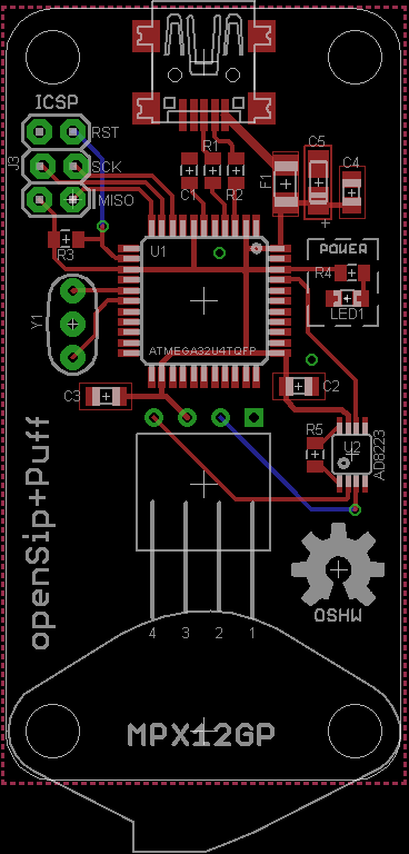
So it looks like something is off with my USB circuit. I used an SMD USB mini-B connector, which was a big pain to solder. I reflowed each of the joints and re-checked the pads and pins with the continuity tester and it looks like each is solidly connected. I still have a hunch that there is something off about the USB circuit, but I don't know what.
Can you verify you are getting 3.3V on pin-6 on the 32U4? That should verify the internal 3.3V USB regulator is enabled for the proper USB data line levels.
Also you should have a 1uF capacitor on pin-6 to GND.
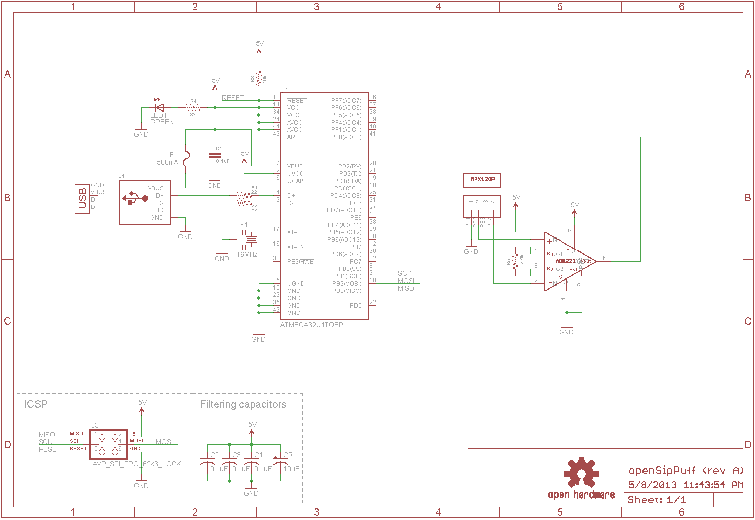
Oh, and there is a 0.1uF capacitor going to ground from pin 6 already. All of the other ATMega32u4 board schematics I could find had a 0.1uF, not a 1uF. Attached the schematic.
Edit: Oh no!! I just checked all the schematics again, and found that only Adafruit's 32u4 breakout has a 0.1uF to ground, all the others have 1uF! Holy smokes that's something.
For my own education, can someone help me understand what this UCAP capacitor does, and why the value may be accounting for this behavior?
UVCC is what the internal 3.3V regulator uses, so it should be at minimum 3.4V to 5.5V max. UVCC is usually tied to VBUS and VCC which is around 5V. If UVCC is only 1.6V that is the problem then.
Are you saying the USB connector VBUS is also measuring around 1.6V?
Did you measure before or after the fuse?
The UCAP is for decoupling the internal 3.3V regulator for USB voltage reference. Atmel recommends a 1uF capacitor.
Sorry, I missed that. With those results it would point to something with the USB connector. There may be a bad connection with either the GND pin-1 or VBUS pin-5 internally to the connector. Do you have a USB breakout cable? It may be that the cable is not contacting correctly in the socket.
Do you have another USB connector? You may need to consider replacing it.
Yes, I agree, smd stuff is not easy. You definitely need to watch for over heating the board or risk lifting the pads. Which may be causing your problems.
I've gotten pretty good at passives down to 0805, SOT-3, TSSOP and TQFP, but with parts that have large pads for mechanical strength (DC power jacks, JST, USB) I can generally get them on, but not off. However I set my soldering station temperature I seem to either have it too hot or too cold for desoldering those huge pads. Oh well, it's a prototype...just an expensive one :S
I removed the the USB connector and soldered the wires from a hacked USB cable onto the pads. Now when I plug in the USB cable my computer recognizes it just fine. I get a USB composite device and a USB input device in my Device Manager.
After I installed the Arduino Leonardo drivers from the Arduino drivers folder I get an Arduino Leonardo device on COM8, which is recognized by the Arduino IDE.
However, when I try to upload the Blink sketch via the Arduino IDE, the COM8 port is dropped and the upload fails. I get the following error:
Binary sketch size: 4,826 bytes (of a 28,672 byte maximum)
processing.app.debug.RunnerException: Couldn’t find a Leonardo on the selected port. Check that you have the correct port selected.  If it is correct, try pressing the board's reset button after initiating the upload.
	at processing.app.debug.AvrdudeUploader.uploadViaBootloader(AvrdudeUploader.java:152)
	at processing.app.debug.AvrdudeUploader.uploadUsingPreferences(AvrdudeUploader.java:67)
	at processing.app.Sketch.upload(Sketch.java:1671)
	at processing.app.Sketch.exportApplet(Sketch.java:1627)
	at processing.app.Sketch.exportApplet(Sketch.java:1599)
	at processing.app.Editor$DefaultExportHandler.run(Editor.java:2380)
	at java.lang.Thread.run(Thread.java:619)
The Leonardo has two different USB drivers, one for the bootloader and one for the core of the sketch program. You should have installed the two Leonardo drivers under two different COM ports. You can check your Device Manager and watch the Ports what drivers shows up. Do you have a reset button on your board? If you hit reset then the Leonardo should disappear and then show up under a different COM port for a few seconds and then disappear and show back under the other COM port.

