I have burnt up a hand full of Arduino Nanos, most of which weren't authentic, trying to figure this out and I am tired of my failed efforts to do so. I am reaching out the the community hoping that someone could help me. I am hoping that it is as simple as adding a diode or something like that but I just need a little guidance.
I have been trying to follow a "guide" [Ender 3 v2 silent fan upgrade][Youtube video where he talks about the wiring] on upgrading the fans on my Ender 3 v2 and everything has worked other than the part when it comes to the PWM part cooling fan being controlled by an Arduino Nano. I believe that I have everything wired up correctly and the code looks good to me. Some people even claim that it worked great for them and for a moment with a fresh Nano it'll work for me... but then it stops working and once I have everything off and touch the Nano it is hot.
The provided wiring diagram from the "guide":

The provided code:
const byte OC1A_PIN = 9; // PWM pin wire to fan
const int inputPin = 4; //sense wire from printer neg fan wire
const word PWM_FREQ_HZ = 25000; //Adjust this value to adjust the frequency
const word TCNT1_TOP = 16000000 / (2 * PWM_FREQ_HZ);

int inputValue = 0;
unsigned long fanFull = 50;
unsigned long fanSpeed = 0;
unsigned long durationHigh = 0;
int durationHighms = 0;
unsigned long durationLow = 0;
int durationLowms = 0;
int durationTotal = 0;
float durationPeriod = 0;
int dutyCycle = 0;

void setup() {
  Serial.begin(115200); //enable the serial monitor

  pinMode(OC1A_PIN, OUTPUT); //set the output pwm pin
  pinMode(inputPin, INPUT_PULLUP); //set the input voltage divider sense pin.

  // Register magic to output at 25KHz
  TCCR1A = 0;
  TCCR1B = 0;
  TCNT1  = 0;
  TCCR1A |= (1 << COM1A1) | (1 << WGM11);
  TCCR1B |= (1 << WGM13) | (1 << CS10);
  ICR1 = TCNT1_TOP;
  Serial.println("Setup completed");
}

void loop()
{
  durationHigh = pulseIn(inputPin, LOW, 1000000);
  durationLow = pulseIn(inputPin, HIGH, 1000000);

  inputValue = digitalRead(inputPin);
  Serial.print(inputValue); //display input voltage as a duty cycle scaled across 25v
  Serial.println(" - inputValue");

  if (durationHigh == 0 && inputValue == LOW) {
    Serial.println("input full");
    fanFull = 100;
  }

  if (durationHigh |= 0) {
    Serial.println("input pulse");
    fanFull = 0;
  }

  if (durationHigh == 0 && inputValue == HIGH) {
    Serial.println("input zero");
    fanFull = 0;
  }

  durationHighms = durationHigh / 1000;
  durationLowms = durationLow / 1000;
  durationTotal = durationHighms + durationLowms;
  durationPeriod = float(durationHighms) / float(durationTotal);
  dutyCycle = durationPeriod * 100;
  fanSpeed = fanFull + dutyCycle;

  //Serial.print(fanSpeed);
  //Serial.println(" - FanSpeed");
  setPwmDuty(fanSpeed);

 /* Serial.print(durationHigh); //display input voltage as a duty cycle scaled across 25v
  Serial.println(" - DurationHigh");

  Serial.print(durationHighms); //display input voltage as a duty cycle scaled across 25v
  Serial.println(" - DurationHighMs");

  Serial.print(durationLow); //display input voltage as a duty cycle scaled across 25v
  Serial.println(" - DurationLow");

  Serial.print(durationLowms); //display input voltage as a duty cycle scaled across 25v
  Serial.println(" - DurationLowMs");

  Serial.print(durationTotal);
  Serial.println(" - Duration Total");

  Serial.print(durationPeriod);
  Serial.println(" - duration period");

  Serial.print(dutyCycle);
  Serial.println(" - duty cycle");

  Serial.print(fanFull);
  Serial.println(" - Fan Full");

  Serial.print(fanSpeed); //display input voltage as a duty cycle scaled across 25v
  Serial.println(" - Duty Cycle");

  Serial.print(fanSpeed);
  Serial.println(" - Fan Speed");
  Serial.println();*/

 // delay(10);
}

void setPwmDuty(byte duty) {
  /*Serial.print(duty);
  Serial.println(" - duty");
  Serial.print(TCNT1_TOP);
  Serial.println(" - TCNT1_TOP");*/

  OCR1A = (word) (duty * TCNT1_TOP) / 100;
  //Serial.print(OCR1A);
  //Serial.println(" - OCR1A");
}
This is how I have the PWM fan and Nano part of this hooked up currently and I am waiting to get another Nano as I type this.
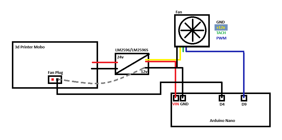
I believe that is issue with the wire which runs from the negative terminal on the 3d printer mobo fan plug to D4 on the Nano and that there is no protection against negative voltages. When I put a multimeter along that gray dashed line I'm getting -22v. I am thinking if I add a diode [fan plug----|<--- D4] that should be fix things but I am not confident in that as the answer with the little bit of knowledge that I have. I am hoping that one of you all could give a little input on if this is the fix or not. Or what the fix would be.
Thank you for any help!


