Hi all
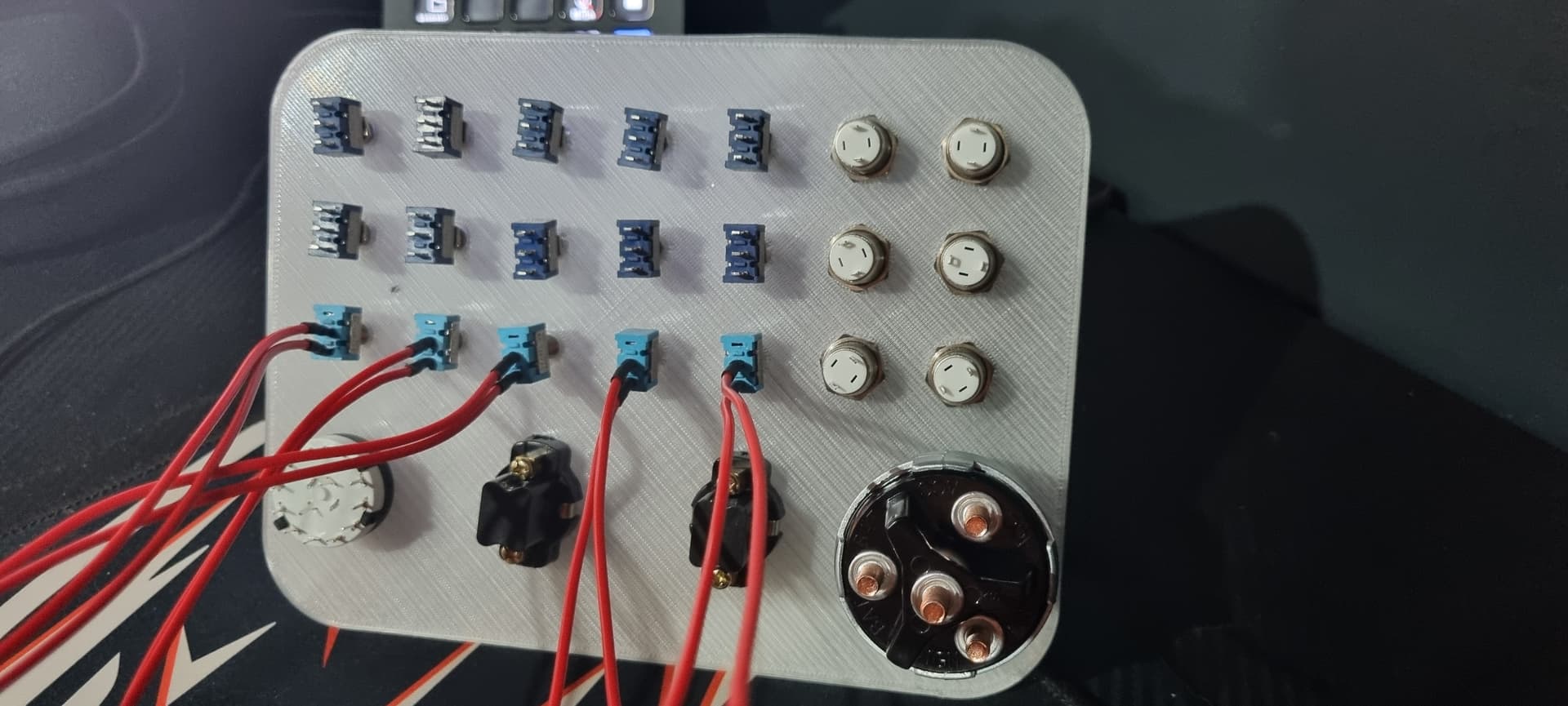
I am very new to all this stuff so need some help from you fellow experts. I have been designing a button box for a trucking simulator, i have got myself a bunch of switches and buttons a 3d printer and ready to roll but i have a few questions. The first onewould be am i limited on how many toggle switches i can use on one board, at the moment i have 15 toggle switches (non momentary), 6 push buttons (momentary) , 2 push pull, 12 position switch and a 4 way ignition switch. also if i upload the design i have could someone show me how i would wired the best way, I will be using my pro micro board. Pointers would be greatly appreciated. Many thanks


No. If you use some extra chips to provide more pins, you can have more buttons/switches.
What are the others?
Post links to the specs of each of these switches. Without those, no-one can tell you how they should be wired.
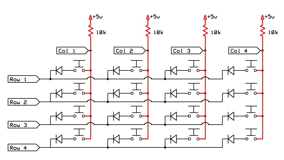
The usual way to connect a large number of buttons & switches is to connect them as a matrix. Since you are using some non-momentary buttons/switches, it will be necessary to wire some small diodes into the matrix.
Awesome thanks for the reply, i did some research and did see about the diodes but not sure on where i would place them in the circuit. All the posts i have seen don't really show much on that side. I will drop the links below of the parts i have, Thanks again
Push Pull Be In Your Mind 5Pcs ASW-05 Single Gear Push-pull Switch Electrical ON-OFF Push-Pull Switch Accessories for Electrical Appliances Tractor 10A DC12V/24V : Amazon.co.uk: DIY & Tools
Ignition MGI SpeedWare 4-Position Universal Ignition Key Switch for 12V Car, Truck, Tractor, Trailer, Forklift - Acc/Off/IGN/(Start) : Amazon.co.uk: Automotive
3 pin toggle QWORK® 20Pcs SPST Mini Toggle Switch AC 125V 6A ON-ON 3 Pins 2 Position for Arduino Boat Vehicles Dash Dashboard (MTS102 Dark Blue) : Amazon.co.uk: Automotive
Push Button Gebildet 10 Pcs 12mm Waterproof Push Button Momentary Stainless Steel Push Button On Off 2A 12V/24V/125V/250V AC (High Head) : Amazon.co.uk: Business, Industry & Science
You would wire a diode in series with any button or switch that's not momentary.
I'm curious what you posted that got flagged!
Those "push-pull" switches. They have 2 positions? If so, you would wire them like any other switch.
That 12-way switch could be the most tricky to deal with as part of the matrix. It might be easier to connect it up as a 12-position potentiometer using 11x 1K resistors and connect the common pin to an analog input pin.
The Discourse forum software flagged the post as possible spam, probably due to the number of external links that it contained
I have removed the flag and restored the post
2 Likes
Can you post link to the 12-position switch please.
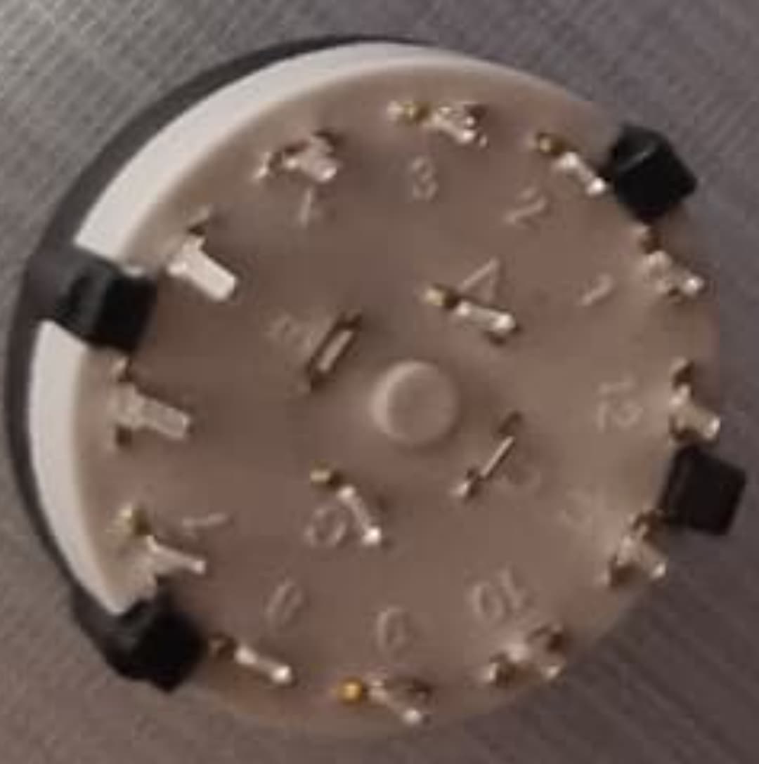
This image looks like it could be a 6 position double throw switch, not a 12 position single throw.
I don't see a problem wiring all the other switch/button types into a 7x4 matrix requiring 11 Arduino pins.
Actually looks like a 3 position-Quadruple-Throw. it is even possible that it can be used in multiple ways
I'm not sure about that. The "A" and "C" terminals seem to have pins, but the "B" and "D" terminals may not have, although it could be just the angle of the picture. No point wasting time trying to figure it out from blurry images, we need that link from @mrmarshall1986 .
I can think of several ways to incorporate the 12-position switch into the matrix.
One way would require a lot of diodes (~20) to encode the 12 outputs down to 4 for inclusion in the matrix.
Another way would be to increase the size of the matrix to at least 12x3, which would require more Arduino pins.
Sorry everyone just been busy at work but can i just say a massive thanks to you all for taking your time to help me out, here's the link for the other switch sourcing map 5PCS 2 Pole 6 Throw 12 Positions 6mm Shaft Diameter Rotary Selector Switch : Amazon.co.uk: DIY & Tools worst case i could just pop in another push pull if this is no good
It could be that the description on the Amazon page is inaccurate. A 12 position switch should be described as "1 pole 12 throw" but this one is described as "2 pole 6 throw". It might have 12 physical positions, but only 6 positions that can be detected by the Arduino (the other 6 positions would read the same as the first 6 positions to the Arduino).
What purpose did you want to use this switch for?
1 Like
I have read your kind reply and here is my contribution from the field.
The Arduino-Due has a large number of I/O pins so that the buttons, switches etc. can be read without additional hardware. This hardware reduces the probability of errors and the system is easier to maintain.
By using OOP you have a nice solution for your simulator.
What do you think?
1 Like
It was mainly for the retarder so you can increase and decrease using this switch. I could use buttons but i guess its more realistic with this type of switch
@paulpaulson that is possibly a better option for me, i will check it out later, thanks again
1 Like
I have (or had) a similar switch from an old velleman kit, which had 3 terminals and was in fact a 4 position triple throw. I was expecting the terminals to have tabs since mine only had A B & C on it.
It's not clear how the switch works, from the Amazon description, which is ambiguous.
If you attach a knob with some pointer on it, how many physical positions does it have? Will it allow you to rotate forever or are there one or two physical stops? If there are stops, what angle can you turn through?
Next, grab your multimeter. Test the switch in each position in turn. For each position, use the multimeter to find out which pin is connected to "A" and which pin is connected to "C", if any. Make a table of the results and post it here.
1 Like
Looking at similar products on the web, it appears there are 1P12T, 2P6T, 4P3T versions that use the same plastic case and have either 1, 2 or 4 pins near the centre and 12 pins around the circumference. But even when there are fewer than 4 pins near the centre, you can see metal stubs where the missing pins would be.
There is also a 3P4T version but that has a different plastic case with 3 pins near the centre.