I am making a button box for my truck simulator but all this is new to me I am trying to figure out how to make a button matrix of how to wire it and then how to make the code for an Arduino micro .
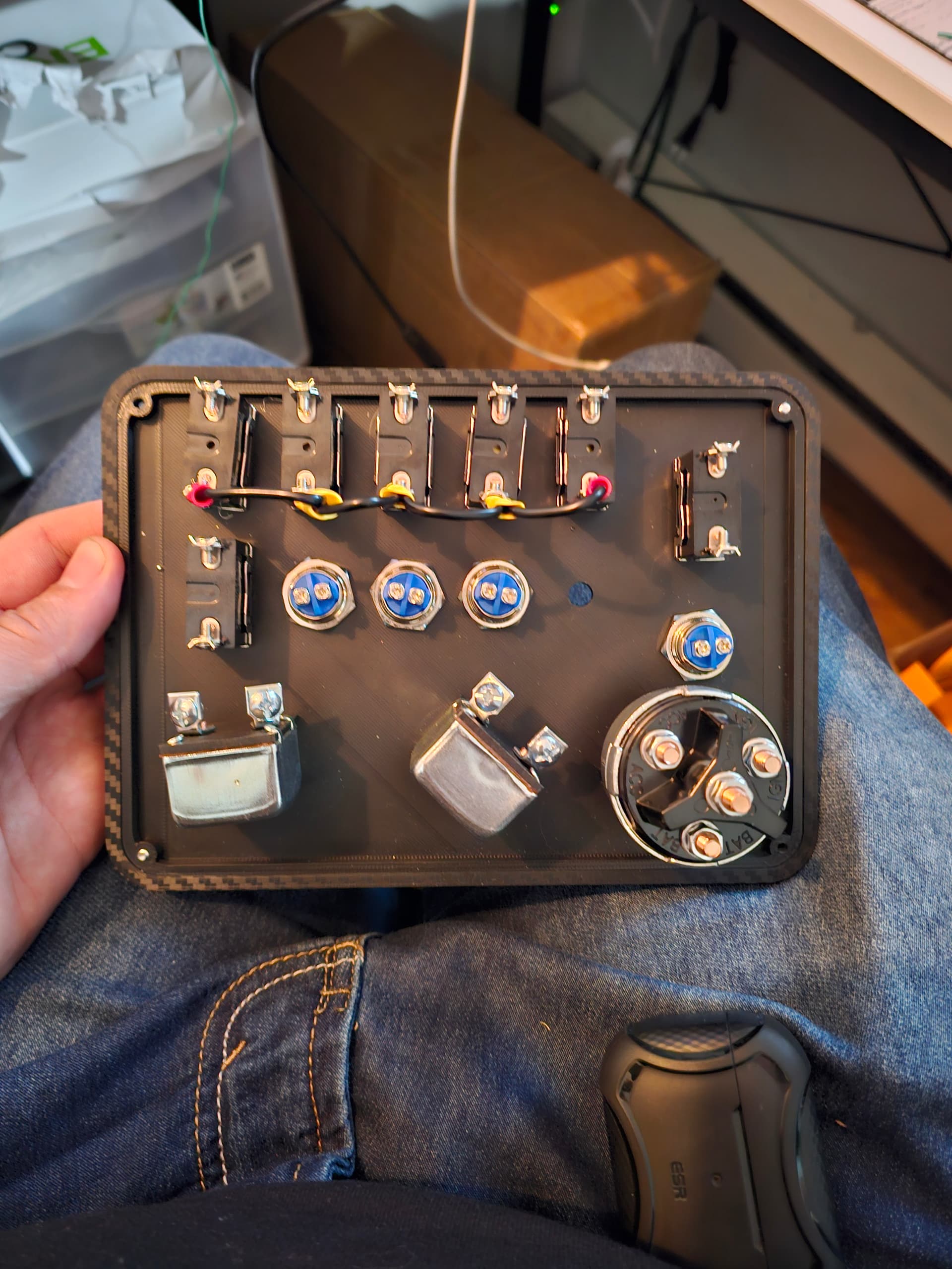
if anyone could possibly help me out I will include a front and back picture of the switch and button configuration I will glady pay someone for their time and help to make this setup work.
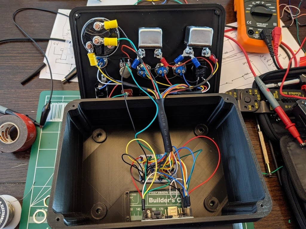
the 3rd picture is pretty much what I want it set up like
basicly i want it to be just on off for the switches and the push buttons work as such a single button press. im trying to figure out if i could just wire them all seperately or what ever or could i like wire 5 switches to the same 2 pins on the micro? like maybe the top row of switches to A1 and pin 2? and then do the same with the push buttons. the parking breaks are push pull switches but i would guess that that works the same as an on off switch? im new to all this i was originally just going to use a usb controller board but it has too many buttons to use one of those. because it woulda been really simple positive and gnd for each switch i dont know much about schematics etc
There are technics using resitance ladders between some 5, 6 buttons using analog reading. Matrixing rocker switches.... Don't remember any easy way for that.
Straight wiring drops some library and is straight forward.
The suggestion is: Go for straight wiring. Else diodes soldered are needed and more complex code.....
so can i just wire all the grounds together to ground and then put each positive to a separate pin? does that work ? i found a sketch for a button box the same but it doesnt show how to actually wire it up
int trailerDiscPin = 2;  // T
int parkBrakePin = 3;    // Z
int trailerBrakePin = 4; // Backslash
int engBrakePin = 5;     // B
int diffLockPin = 6;     // V
int dropAxlePin = 7;     // U
int trailerAxlePin = 8;  // .
int beaconPin = 9;       // O
int hazardsPin = 10;     // F
int lightsPin = 11;      // L
int wipersPin = 12;      // P
int displayPin = 13;     // I

// REFUEL                   Slash
// VOLUME UP                ]
// VOLUME DOWN              [
// ENGINE START/STOP        E

// Initial states for external resistor switches
int trailerDiscState = LOW;

// Initial states for internal resistor switches
int parkBrakeState = HIGH;
int trailerBrakeState = HIGH;
int engBrakeState = HIGH;
int diffLockState = HIGH;
int dropAxleState = HIGH;
int trailerAxleState = HIGH;
int beaconState = HIGH;
int hazardsState = HIGH;
int lightsState = HIGH;
int wipersState = HIGH;
int displayState = HIGH;

int lightPush = 0;
int wiperPush = 0;
int displayPush = 0;

int volValue = 0;
int ignState = 0;
int strState = 0;

// the setup routine runs once when you press reset:
void setup() {
  // initialize serial communication at 115200 bits per second:
  Serial.begin(115200);

  // These pins use an external resistor
  pinMode(trailerDiscPin, INPUT);

  // These pins use the internal pullup resistor
  pinMode(parkBrakePin, INPUT_PULLUP);
  pinMode(trailerBrakePin, INPUT_PULLUP);
  pinMode(engBrakePin, INPUT_PULLUP);
  pinMode(diffLockPin, INPUT_PULLUP);
  pinMode(dropAxlePin, INPUT_PULLUP);
  pinMode(trailerAxlePin, INPUT_PULLUP);
  pinMode(beaconPin, INPUT_PULLUP);
  pinMode(hazardsPin, INPUT_PULLUP);
  pinMode(lightsPin, INPUT_PULLUP);
  pinMode(wipersPin, INPUT_PULLUP);
  pinMode(displayPin, INPUT_PULLUP);

  volValue = analogRead(A0);
}

// the loop routine runs over and over again forever:
void loop() {
  int trailerDisc = digitalRead(trailerDiscPin);
  int parkBrake = digitalRead(parkBrakePin);
  int trailerBrake = digitalRead(trailerBrakePin);
  int trailerAxle = digitalRead(trailerAxlePin);
  int beacon = digitalRead(beaconPin);
  int hazards = digitalRead(hazardsPin);
  int dropAxle = digitalRead(dropAxlePin);
  int diffLock = digitalRead(diffLockPin);
  int engBrake = digitalRead(engBrakePin);
  int lights = digitalRead(lightsPin);
  int wipers = digitalRead(wipersPin);
  int disp = digitalRead(displayPin);

  // Check for released buttons
  if (lights == HIGH)
    lightPush = 0;
  if (wipers == HIGH)
    wiperPush = 0;
  if (disp == HIGH)
    displayPush = 0;

  //Trailer Disconnect
  if (trailerDisc != trailerDiscState)
  {
    Serial.write('t');
    trailerDiscState = trailerDisc;
  }
  //Parking Brake
  if (parkBrake != parkBrakeState){
    Serial.write('z');
    parkBrakeState = parkBrake;
  }
  //Trailer Brake
  if (trailerBrake != trailerBrakeState){
    Serial.write('\\');
    trailerBrakeState = trailerBrake;
  }
  //Trailer Axle
  if (trailerAxle != trailerAxleState){
    Serial.write('.');
    trailerAxleState = trailerAxle;
    }
  //Beacon
  if (beacon != beaconState){
    Serial.write('o');
    beaconState = beacon;
  }
  //Hazards
  if (hazards != hazardsState){
    Serial.write('f');
    hazardsState = hazards;
  }
  //Drop Axle
  if (dropAxle != dropAxleState){
    Serial.write('u');
    dropAxleState = dropAxle;
  }
  //Diff Lock
  if (diffLock != diffLockState){
    Serial.write('v');
    diffLockState = diffLock;
  }
  //Engine Brake
  if (engBrake != engBrakeState){
    Serial.write('b');
    engBrakeState = engBrake;
  }

  //Lights
  if (lights == LOW && lightPush == 0)
  {
    Serial.write('l');
    lightPush = 1;
  }
  //Wipers
  if (wipers == LOW && wiperPush == 0)
  {
    Serial.write('p');
    wiperPush = 1;
  }
  //Display
  if (disp == LOW && displayPush == 0)
  {
    Serial.write('i');
    displayPush = 1;
  }

  // Refuel
  int refuelValue = analogRead(A2);
  if (refuelValue == 0)
  {
    while (refuelValue == 0) {
      Serial.write('/');
      refuelValue = analogRead(A2);
    }
  }

  // Read in the volume
  int newVolValue = analogRead(A0);
  // Calculate the difference
  int volDiff = newVolValue - volValue;
  // If the difference is positive...
  // (25 to denoise)
  if (volDiff > 25)
  {
    Serial.write(']');
    volValue = newVolValue;
  }
  // If the difference is negative...
  // (25 to denoise)
  else if (volDiff < -25)
  {
    Serial.write('[');
    volValue = newVolValue;
  }

  // Ignition
  int ign = analogRead(A5);
  int str = analogRead(A4);
  if (ign > 500 && str > 500 && ignState == 1)
  {
    Serial.write('e');
    ignState = 0;
    strState = 0;
  }
  if (str < 10 && ignState == 1 && strState != 1)
  {
    Serial.write('e');
    strState = 1;
  }
  if (ign < 100 && ignState != 1)
  {
     Serial.write('e');
     ignState = 1;
  }

  delay(50);        // delay in between reads for stability
}
so does this mean i run positive of each toggle to the pins of choice? but what do i do with the grounds. all of the switches are 2 wire switches. i am a complete dummy im trying to figure this stuff out but sadly im a truck driver and i honestly dont have alot of learning time other then the odd weekend when im home lol i used to know alot of this stuff when i was younger but lost it all sadly
ok so i found more info on this project i have all the same switches and buttons i dont have an arduino uno or a breadboard or what ever thats called but i realllly dont understand the drawings. is there any way to compute them into how to wire this up using a pro micro leonard? or could you possibly tell me how i would actually wire this thing i have no issue buying a uno if i have too i just dont understand the electrical stuff at all im trying to learn about it but i am a complete noob and obviously not that bright lol. thank you for all the help so far it is greatly appreciated
Please make a simple list of each different kind of switch or button, and any LEDs you want, along with the number of them you want to have in your final device.
For automotive switches that do things like ignition key sequencing off/start/run or that control a light in addition to affording an on/off switching capability, state the exact make and model… those switches work perfectly in their normal deployment; using them in a button box requires knowing more about their innards.
If you want to understand what you are doing rather than slavishly copying a working button box or being spoon fed code line by line here, which will get old fast, I suggest you divide your time between making progress on your device and learning about programming the Arduino without worrying about accomplishing anything but learning.
Right now, I would recommend 100 percent learning time to 0 percent dreaming and thinking and hacking. Realistically I know this is hard, so mebbe shoot for 75/25 split.
In the IDE there are examples that start from zero. No one was born knowing anything about this, some of us will admit to learning something almost every day after years.
With a few parts, you can try doing things like making a LED go on and off when you flip a switch, then making it go on when you press a button and off when you press the button again.
Those two ridiculous mini-projects may take you more time than you want to spend, but such time spent will return the investment many fold.
You can even do it without buying a single part. The wokwi simulator is easier to use than fiddling with a bread box and wires and LEDs and pushbuttons, and it will allow you to focus on the software without hardware issues like broken parts or dodgy power supplies or whatever:
Thank you very much for your post on this ! i agree with you taking the time to learn is best as well i dont have a timeline really on how long to do this. my only issue is the amount i work and not having internet service alot of the time when i park for the night so sadly my only time is on the weekends i make it home mostly but i am willing to learn for sure it will just take time!
also thank you for the simulator that will most definitely help!!!!
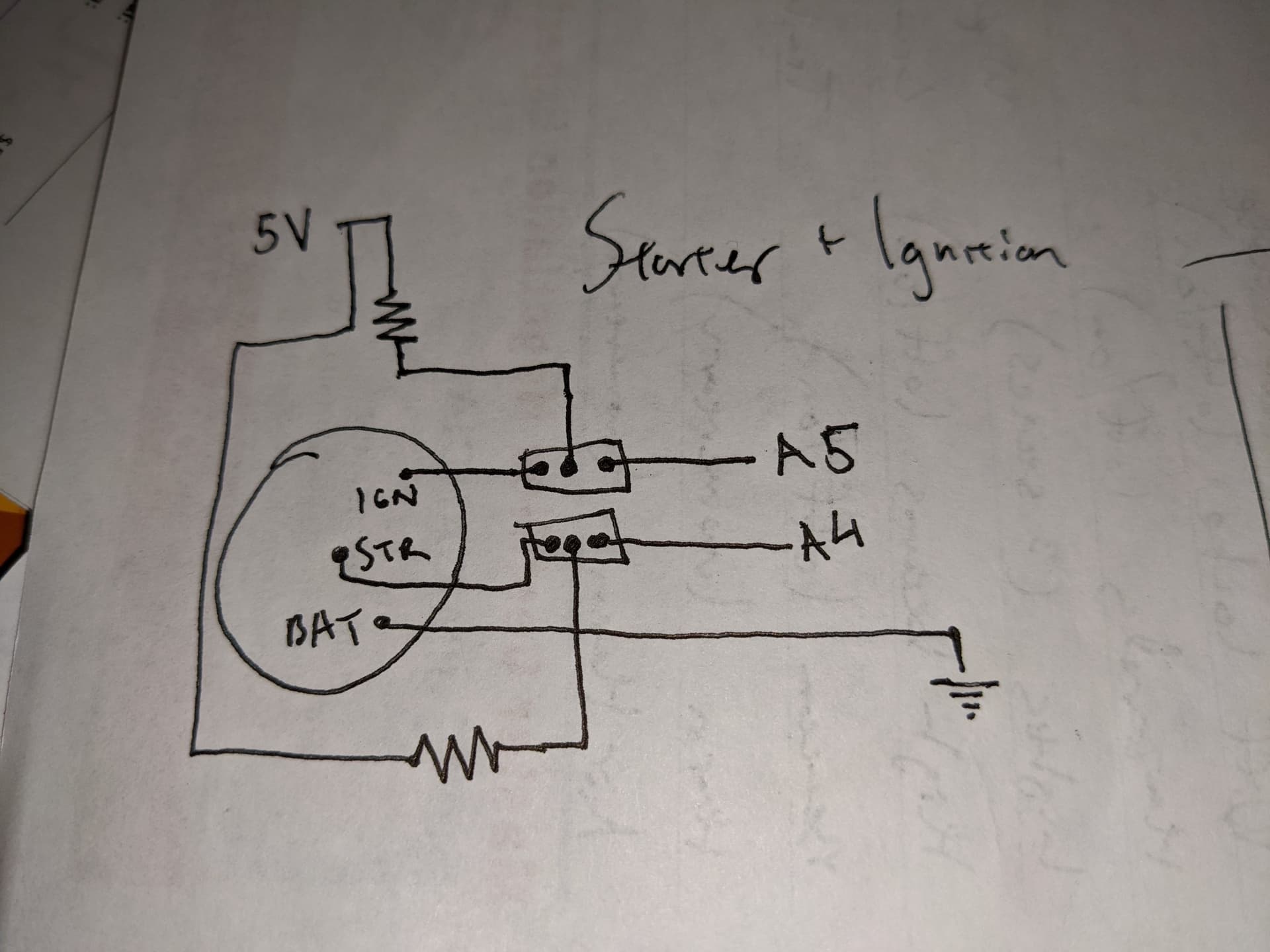
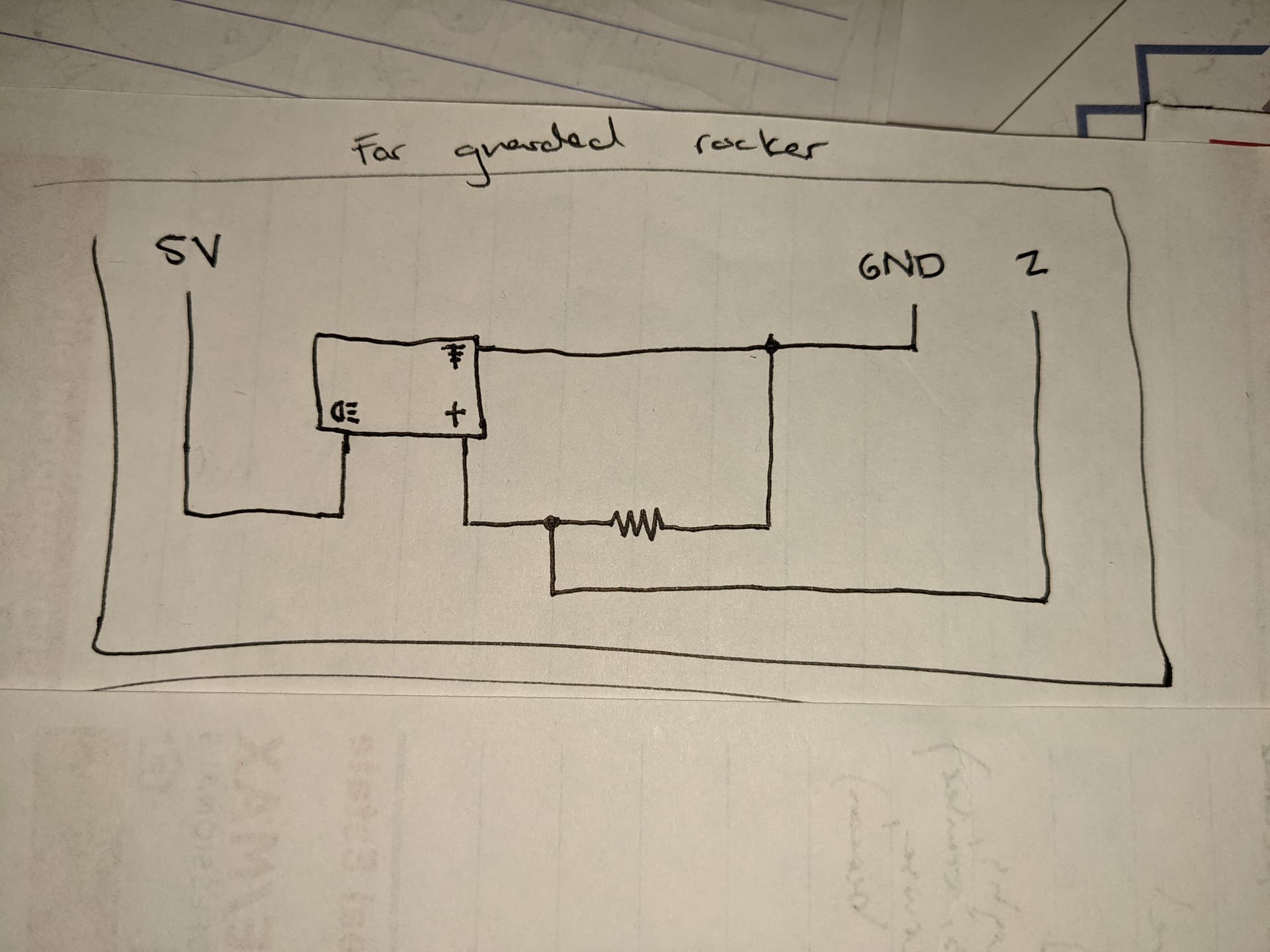
Your pictures in reply #12....
The first picture. The "Bat" cable to GND is likely the middle finger in a rocker switch. Use digital input and INPUT_PULLUP to read it.
The second picture..... Which one of Your switches, or buttons, will that be?
Well all my switches are 2 post switches so im wondering if i should swap them out for 3 finger ones?? The top 7 switches are the just on off toggles but i think the trailer disconnect maybe should be changed to a 3 pin rocker if im correct with that drawing ? Those drawings and the picture are from the original builder of the same kind of box but i dont understand them. At all. I and going to look into it some more thank you all soo much for your input its helping immensely.
How did you put those brake knobs on the push pull switches? i want to know because i can't figure out how to, and i am getting ready to build my button box