Hello again!
I am attempting to work towards a goal of making a joystick "button box" (as you've seen many a youtube video of, and probably a million forum posts).
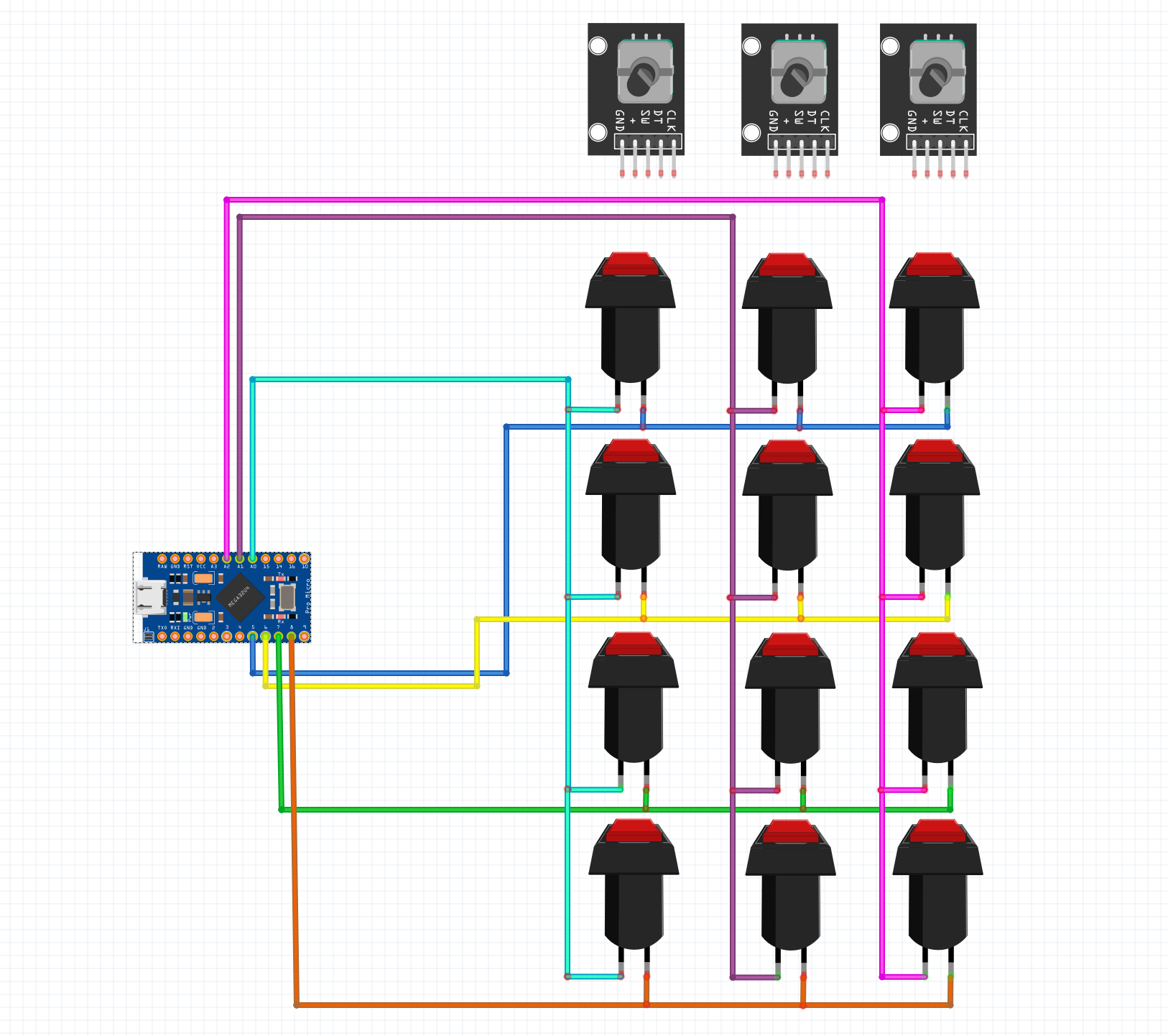
Before I go into the coding aspect of everything, I wanted to see if you guys could check and see if my button matrix is correct. This would be my first time attempting something of the sort, so I want to make sure I'm good to go:
The Code would look something like this:
#include <Keypad.h>
#include <Joystick.h>

//DEFINITIONS
#define ENABLE_PULLUPS
#define NUMROTARIES 3 //replace "?" with number of rotary encoders you are using
#define NUMBUTTONS 12 //replace "?"with number of buttong you are using
#define NUMROWS 4 //replace "?" with number of rows you have
#define NUMCOLS 3 //replace "?" with number of columns you have
//BUTTON MATRIX
//first change number of rows and columns to match your button matrix,
//then replace all "?" with numbers (starting from 0)
byte buttons[NUMROWS][NUMCOLS] = {
  {0,1,2},
  {3,4,5},
  {6,7,8},
  {9,10,11}
};

struct rotariesdef {
  byte pin1;
  byte pin2;
  int ccwchar;
  int cwchar;
  volatile unsigned char state;
};

//ROTARY ENCODERS
//each line controls a different rotary encoder
//the first two numbers refer to the pins the encoder is connected to
//the second two are the buttons each click of the encoder wil press
//do NOT exceed 31 for the final button number
rotariesdef rotaries[NUMROTARIES] {
  {3,4,22,23,0}, //rotary 1
  {15,14,24,25,0}, //rotary 2
  {16,10,26,27,0}, //rotary 3


};

#define DIR_CCW 0x10
#define DIR_CW 0x20
#define R_START 0x0

#ifdef HALF_STEP
#define R_CCW_BEGIN 0x1
#define R_CW_BEGIN 0x2
#define R_START_M 0x3
#define R_CW_BEGIN_M 0x4
#define R_CCW_BEGIN_M 0x5
const unsigned char ttable[6][4] = {
  // R_START (00)
  {R_START_M,            R_CW_BEGIN,     R_CCW_BEGIN,  R_START},
  // R_CCW_BEGIN
  {R_START_M | DIR_CCW, R_START,        R_CCW_BEGIN,  R_START},
  // R_CW_BEGIN
  {R_START_M | DIR_CW,  R_CW_BEGIN,     R_START,      R_START},
  // R_START_M (11)
  {R_START_M,            R_CCW_BEGIN_M,  R_CW_BEGIN_M, R_START},
  // R_CW_BEGIN_M
  {R_START_M,            R_START_M,      R_CW_BEGIN_M, R_START | DIR_CW},
  // R_CCW_BEGIN_M
  {R_START_M,            R_CCW_BEGIN_M,  R_START_M,    R_START | DIR_CCW},
};
#else
#define R_CW_FINAL 0x1
#define R_CW_BEGIN 0x2
#define R_CW_NEXT 0x3
#define R_CCW_BEGIN 0x4
#define R_CCW_FINAL 0x5
#define R_CCW_NEXT 0x6

const unsigned char ttable[7][4] = {
  // R_START
  {R_START,    R_CW_BEGIN,  R_CCW_BEGIN, R_START},
  // R_CW_FINAL
  {R_CW_NEXT,  R_START,     R_CW_FINAL,  R_START | DIR_CW},
  // R_CW_BEGIN
  {R_CW_NEXT,  R_CW_BEGIN,  R_START,     R_START},
  // R_CW_NEXT
  {R_CW_NEXT,  R_CW_BEGIN,  R_CW_FINAL,  R_START},
  // R_CCW_BEGIN
  {R_CCW_NEXT, R_START,     R_CCW_BEGIN, R_START},
  // R_CCW_FINAL
  {R_CCW_NEXT, R_CCW_FINAL, R_START,     R_START | DIR_CCW},
  // R_CCW_NEXT
  {R_CCW_NEXT, R_CCW_FINAL, R_CCW_BEGIN, R_START},
};
#endif

//BUTTON MATRIX PART 2
byte rowPins[NUMROWS] = {5,6,7,8}; //change "?" to the pins the rows of your button matrix are connected to
byte colPins[NUMCOLS] = {A0,A1,A2}; //change "?" to the pins the rows of your button matrix are connected to

Keypad buttbx = Keypad( makeKeymap(buttons), rowPins, colPins, NUMROWS, NUMCOLS);

//JOYSTICK SETTINGS
Joystick_ Joystick(JOYSTICK_DEFAULT_REPORT_ID,
  JOYSTICK_TYPE_JOYSTICK,
  32, //number of buttons
  0, //number of hat switches
  //Set as many axis to "true" as you have potentiometers for
  false, // y axis
  false, // x axis
  false, // z axis
  false, // rx axis
  false, // ry axis
  false, // rz axis
  false, // rudder
  false, // throttle
  false, // accelerator
  false, // brake
  false); // steering wheel

const int numReadings = 20;

int readings[numReadings];      // the readings from the analog input
int index = 0;              // the index of the current reading
int total = 0;                  // the running total
int currentOutputLevel = 0;

//POTENTIOMETERS PART 1
//add all the axis' which are enabled above
int zAxis_ = 0;
int RxAxis_ = 0;


//POTENTIOMETERS  PART 2
//Which pins are your potentiometers connected to?
//int potentiometerPin1 = ?; //Change "?" to the pin your potentiometer is connected to
//int potentiometerPin2 = ?;
//const bool initAutoSendState = true;


void setup() {
  Joystick.begin();
  rotary_init();
  for (int thisReading = 0; thisReading < numReadings; thisReading++) {
    readings[thisReading] = 0;
  }
}

void loop() {

  CheckAllEncoders();
  CheckAllButtons();
  CheckAllPotentiometers();

}

//POTENTIOMETERS PART 3
//change the details to match teh details above for each potentiometer you are using
void CheckAllPotentiometers(){

  //potentiometer 1
//  currentOutputLevel = getAverageOutput(potentiometerPin1);
//  zAxis_ = map(currentOutputLevel,0,1023,0,255);
//  Joystick.setZAxis(zAxis_);

  //potentiometer 2
//  currentOutputLevel = getAverageOutput(potentiometerPin2);
//  RxAxis_ = map(currentOutputLevel,0,1023,0,255);
//  Joystick.setRxAxis(RxAxis_);


}

int getAverageOutput(int pinToRead){
  index = 0;
  total = 0;

  while (index < numReadings){
    readings[index] = analogRead(pinToRead);
    total = total + readings[index];
    index = index + 1;
    //delay (1);
  }
  return total / numReadings;
}


void CheckAllButtons(void) {
      if (buttbx.getKeys())
    {
       for (int i=0; i<LIST_MAX; i++)
        {
           if ( buttbx.key[i].stateChanged )
            {
            switch (buttbx.key[i].kstate) {
                    case PRESSED:
                    case HOLD:
                              Joystick.setButton(buttbx.key[i].kchar, 1);
                              break;
                    case RELEASED:
                    case IDLE:
                              Joystick.setButton(buttbx.key[i].kchar, 0);
                              break;
            }
           }
         }
     }
}


void rotary_init() {
  for (int i=0;i<NUMROTARIES;i++) {
    pinMode(rotaries[i].pin1, INPUT);
    pinMode(rotaries[i].pin2, INPUT);
    #ifdef ENABLE_PULLUPS
      digitalWrite(rotaries[i].pin1, HIGH);
      digitalWrite(rotaries[i].pin2, HIGH);
    #endif
  }
}


unsigned char rotary_process(int _i) {
  //Serial.print("Processing rotary: ");
  //Serial.println(_i);
  unsigned char pinstate = (digitalRead(rotaries[_i].pin2) << 1) | digitalRead(rotaries[_i].pin1);
  rotaries[_i].state = ttable[rotaries[_i].state & 0xf][pinstate];
  return (rotaries[_i].state & 0x30);
}

void CheckAllEncoders(void) {
  Serial.println("Checking rotaries");
  for (int i=0;i<NUMROTARIES;i++) {
    unsigned char result = rotary_process(i);
    if (result == DIR_CCW) {
      Serial.print("Rotary ");
      Serial.print(i);
      Serial.println(" <<< Going CCW");
      Joystick.setButton(rotaries[i].ccwchar, 1); delay(50); Joystick.setButton(rotaries[i].ccwchar, 0);
    };
    if (result == DIR_CW) {
      Serial.print("Rotary ");
      Serial.print(i);
      Serial.println(" >>> Going CW");
      Joystick.setButton(rotaries[i].cwchar, 1); delay(50); Joystick.setButton(rotaries[i].cwchar, 0);
    };
  }
  Serial.println("Done checking");
}
Can someone look over this and see if I'm on the correct path here? Please note that I'm omitting the potentiometers because I don't plan on using them in this build.
Also you'll note that there are 3 rotary encoders. Can anyone walk me through how the 5 pinout is connected to the Arduino here? Most rotary encoders I see have 2 pins being connected.
Thank you everyone so much in advance. I am having a lot of fun!