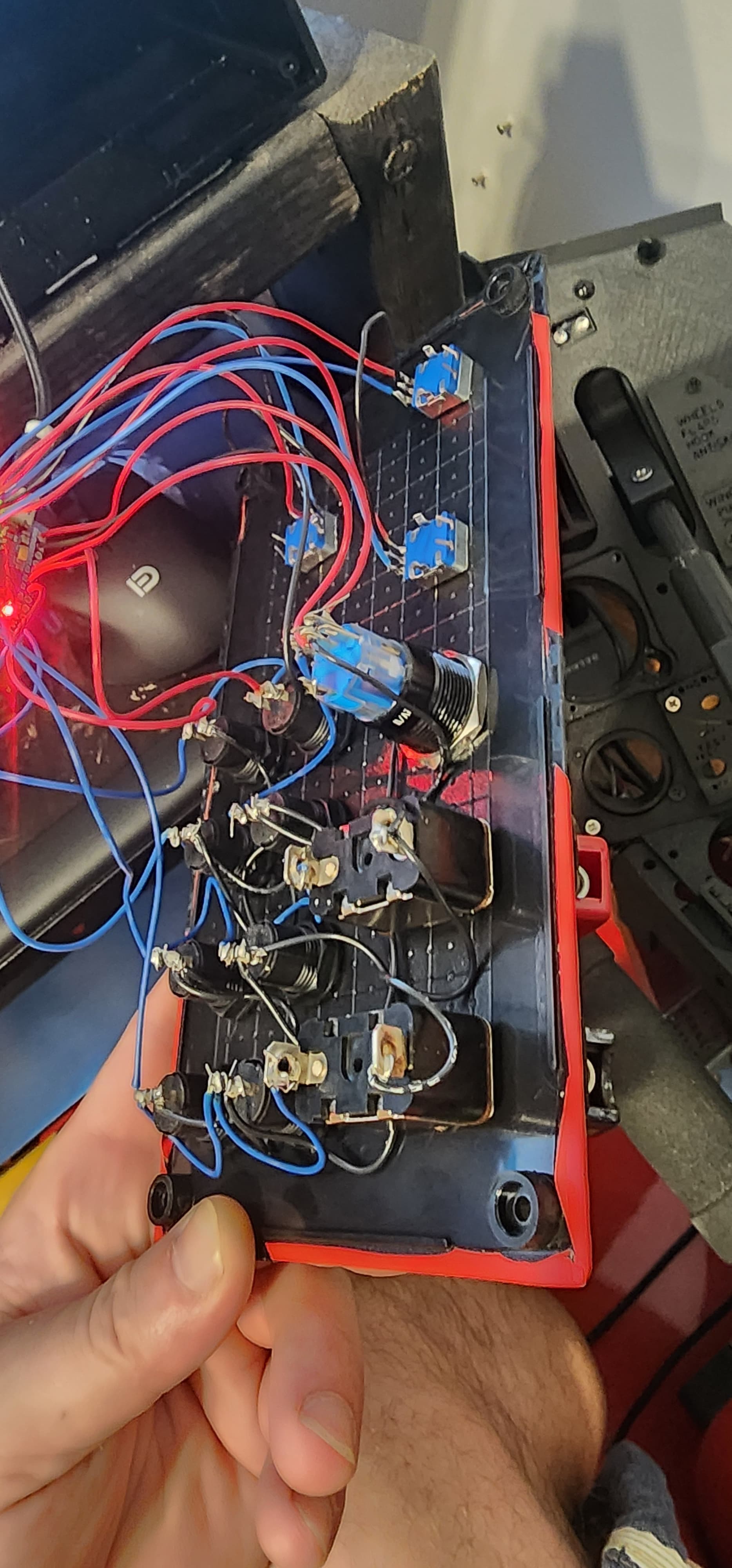
so i was coding for an iron man helmet wrote over the wrong code and now im stuck. lol ive opened her up and its a matrix style wiring is there any way i can get someone to write me up a code i have no idea whatsoever with what im doing.
- Trace each wire.
- Label where it starts and where it ends.
- Label devices.
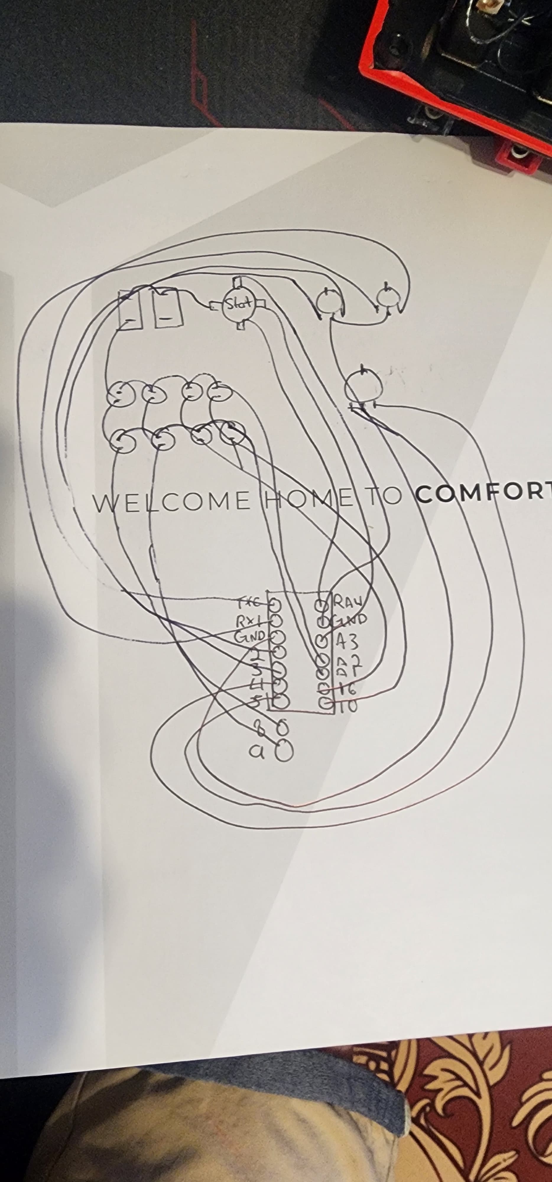
- Draw a wiring diagram.
- Write code (with help).
Have you asked the organization from whom you won the device if they can put you in contact with the creator? They can probably email you the file.
I thought the same thing right away the discord is shutdown and i cant find the email where i was in contact with the person.

Good start. Make it legible.
haha your right i tried to read my own diagram couldn't do it.
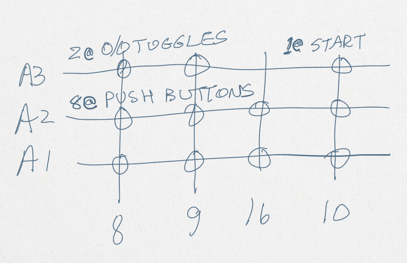
a3 is Normally open and Closed is attached to push button indicated as yellow on illuminated start engine push button.
Draw a circuit diagram.
Just one example here .....
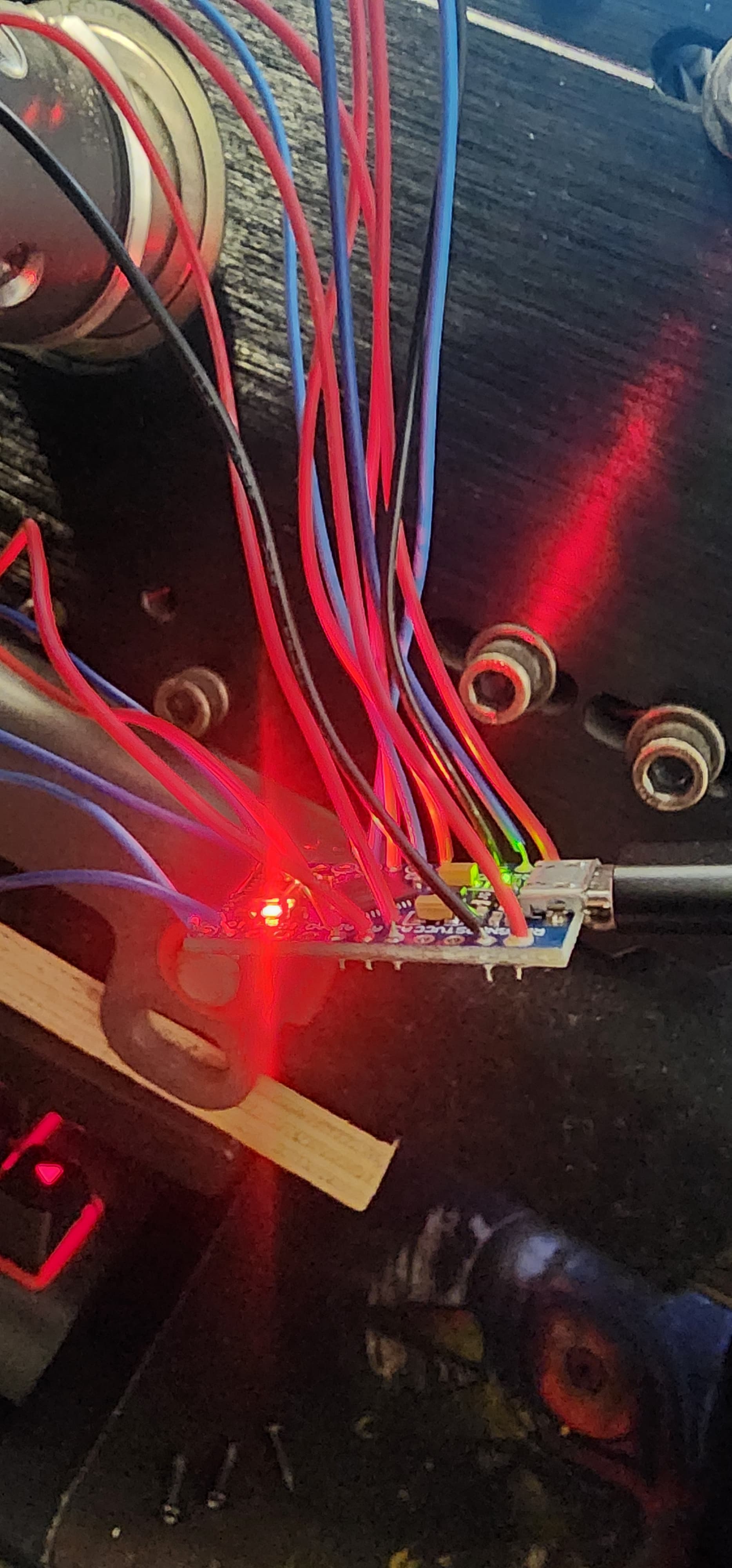
The "pushbutton" with four wires... is connected to RAW... which is a Vin pin... how is power showing at the pin to pass power to RAW?
RAW is the unregulated voltage input for the Pro Micro. If the board is powered via USB, the voltage at this pin will be about 4.8V (USB's 5V minus a schottkey diode drop). On the other hand, if the board is powered externally, through this pin, the applied voltage can be up to 12V.
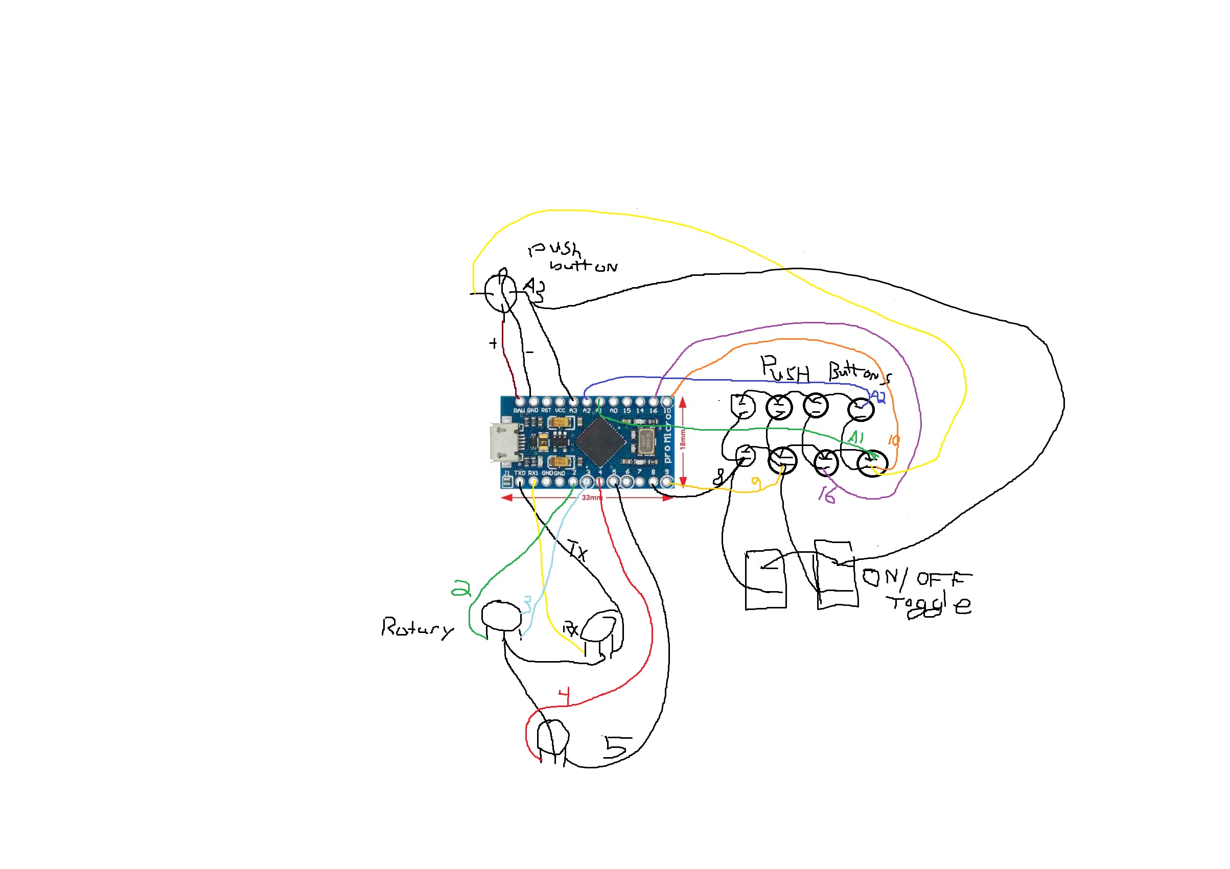
The nine pushbuttons and two toggle switches are in matrix configuration. With the toggle switches I would expect to see diodes, they would be useful even if there were only momentary pushbuttons.
But I make no sense of the "rotary" devices depicted - what is the involvement with TX0 and RX1 all about?
And code can be written only if… you say what it is supposed to do.
a7
1 Like
Does it look something like this: Button Box Schematic found by a Google image search which turned up 100s of examples.
Search on: arduino button box
so i did search and try 3 or 4 different codes but i was getting an error withe the joystick and keypad libraries. when it comes to coding i am a potato, i usually buy leo bodnar boards as game device controllers. at the point i just dont know how to get the matrix code to work with my board.
so there rotary encoders the whole setup is used as a game device controller aka "button box". i hope this answers your question i got the item given to me or i would have followed another diagram with code already written. if you need anything else il keep an eye out to answer quickly i do appreciate the help!
#include <Keypad.h>
#include <Joystick.h>

//DEFINITIONS
#define ENABLE_PULLUPS
#define NUMROTARIES 3 //replace "?" with number of rotary encoders you are using
#define NUMBUTTONS 13 //replace "?"with number of buttong you are using
#define NUMROWS 3 //replace "?" with number of rows you have
#define NUMCOLS 6 //replace "?" with number of columns you have

//BUTTON MATRIX
//first change number of rows and columns to match your button matrix,
//then replace all "?" with numbers (starting from 0)
byte buttons[NUMROWS][NUMCOLS] = {
  {0, 1, 2, 3, 4, 5},
  {6, 7, 8, 9, 10, 11},
  {12, 13, 14, 15, 16, 17}


};

struct rotariesdef {
  byte pin1;
  byte pin2;
  int ccwchar;
  int cwchar;
  volatile unsigned char state;
};

//ROTARY ENCODERS
//each line controls a different rotary encoder
//the first two numbers refer to the pins the encoder is connected to
//the second two are the buttons each click of the encoder wil press
//do NOT exceed 31 for the final button number
rotariesdef rotaries[NUMROTARIES] {
  {0, 1, 22, 23, 0}, //rotary 1
  {2, 3, 24, 25, 0}, //rotary 2
  {4, 5, 26, 27, 0}, //rotary 3


};

#define DIR_CCW 0x10
#define DIR_CW 0x20
#define R_START 0x0

#ifdef HALF_STEP
#define R_CCW_BEGIN 0x1
#define R_CW_BEGIN 0x2
#define R_START_M 0x3
#define R_CW_BEGIN_M 0x4
#define R_CCW_BEGIN_M 0x5
const unsigned char ttable[6][4] = {
  // R_START (00)
  {R_START_M,            R_CW_BEGIN,     R_CCW_BEGIN,  R_START},
  // R_CCW_BEGIN
  {R_START_M | DIR_CCW, R_START,        R_CCW_BEGIN,  R_START},
  // R_CW_BEGIN
  {R_START_M | DIR_CW,  R_CW_BEGIN,     R_START,      R_START},
  // R_START_M (11)
  {R_START_M,            R_CCW_BEGIN_M,  R_CW_BEGIN_M, R_START},
  // R_CW_BEGIN_M
  {R_START_M,            R_START_M,      R_CW_BEGIN_M, R_START | DIR_CW},
  // R_CCW_BEGIN_M
  {R_START_M,            R_CCW_BEGIN_M,  R_START_M,    R_START | DIR_CCW},
};
#else
#define R_CW_FINAL 0x1
#define R_CW_BEGIN 0x2
#define R_CW_NEXT 0x3
#define R_CCW_BEGIN 0x4
#define R_CCW_FINAL 0x5
#define R_CCW_NEXT 0x6

const unsigned char ttable[7][4] = {
  // R_START
  {R_START,    R_CW_BEGIN,  R_CCW_BEGIN, R_START},
  // R_CW_FINAL
  {R_CW_NEXT,  R_START,     R_CW_FINAL,  R_START | DIR_CW},
  // R_CW_BEGIN
  {R_CW_NEXT,  R_CW_BEGIN,  R_START,     R_START},
  // R_CW_NEXT
  {R_CW_NEXT,  R_CW_BEGIN,  R_CW_FINAL,  R_START},
  // R_CCW_BEGIN
  {R_CCW_NEXT, R_START,     R_CCW_BEGIN, R_START},
  // R_CCW_FINAL
  {R_CCW_NEXT, R_CCW_FINAL, R_START,     R_START | DIR_CCW},
  // R_CCW_NEXT
  {R_CCW_NEXT, R_CCW_FINAL, R_CCW_BEGIN, R_START},
};
#endif

//BUTTON MATRIX PART 2
byte rowPins[NUMROWS] = {8, 7, 6}; //change "?" to the pins the rows of your button matrix are connected to
byte colPins[NUMCOLS] = {A0, A1, A2, A3, A9, A10}; //change "?" to the pins the rows of your button matrix are connected to

Keypad buttbx = Keypad( makeKeymap(buttons), rowPins, colPins, NUMROWS, NUMCOLS);

//JOYSTICK SETTINGS
Joystick_ Joystick(JOYSTICK_DEFAULT_REPORT_ID,
                   JOYSTICK_TYPE_JOYSTICK,
                   32, //number of buttons
                   0, //number of hat switches
                   //Set as many axis to "true" as you have potentiometers for
                   false, // y axis
                   false, // x axis
                   false, // z axis
                   false, // rx axis
                   false, // ry axis
                   false, // rz axis
                   false, // rudder
                   false, // throttle
                   false, // accelerator
                   false, // brake
                   false); // steering wheel

const int numReadings = 20;

int readings[numReadings];      // the readings from the analog input
int index = 0;              // the index of the current reading
int total = 0;                  // the running total
int currentOutputLevel = 0;

//POTENTIOMETERS PART 1
//add all the axis' which are enabled above
int zAxis_ = 0;
int RxAxis_ = 0;


//POTENTIOMETERS  PART 2
//Which pins are your potentiometers connected to?
int potentiometerPin1 = ?; //Change "?" to the pin your potentiometer is connected to
int potentiometerPin2 = ?;
const bool initAutoSendState = true;


void setup() {
  Joystick.begin();
  rotary_init();
  for (int thisReading = 0; thisReading < numReadings; thisReading++) {
    readings[thisReading] = 0;
  }
}

void loop() {

  CheckAllEncoders();
  CheckAllButtons();
  CheckAllPotentiometers();

}

//POTENTIOMETERS PART 3
//change the details to match teh details above for each potentiometer you are using
void CheckAllPotentiometers() {

  //potentiometer 1
  currentOutputLevel = getAverageOutput(potentiometerPin1);
  zAxis_ = map(currentOutputLevel, 0, 1023, 0, 255);
  Joystick.setZAxis(zAxis_);

  //potentiometer 2
  currentOutputLevel = getAverageOutput(potentiometerPin2);
  RxAxis_ = map(currentOutputLevel, 0, 1023, 0, 255);
  Joystick.setRxAxis(RxAxis_);


}

int getAverageOutput(int pinToRead) {
  index = 0;
  total = 0;

  while (index < numReadings) {
    readings[index] = analogRead(pinToRead);
    total = total + readings[index];
    index = index + 1;
    //delay (1);
  }
  return total / numReadings;
}


void CheckAllButtons(void) {
  if (buttbx.getKeys())
  {
    for (int i = 0; i < LIST_MAX; i++)
    {
      if ( buttbx.key[i].stateChanged )
      {
        switch (buttbx.key[i].kstate) {
          case PRESSED:
          case HOLD:
            Joystick.setButton(buttbx.key[i].kchar, 1);
            break;
          case RELEASED:
          case IDLE:
            Joystick.setButton(buttbx.key[i].kchar, 0);
            break;
        }
      }
    }
  }
}


void rotary_init() {
  for (int i = 0; i < NUMROTARIES; i++) {
    pinMode(rotaries[i].pin1, INPUT);
    pinMode(rotaries[i].pin2, INPUT);
#ifdef ENABLE_PULLUPS
    digitalWrite(rotaries[i].pin1, HIGH);
    digitalWrite(rotaries[i].pin2, HIGH);
#endif
  }
}


unsigned char rotary_process(int _i) {
  //Serial.print("Processing rotary: ");
  //Serial.println(_i);
  unsigned char pinstate = (digitalRead(rotaries[_i].pin2) << 1) | digitalRead(rotaries[_i].pin1);
  rotaries[_i].state = ttable[rotaries[_i].state & 0xf][pinstate];
  return (rotaries[_i].state & 0x30);
}

void CheckAllEncoders(void) {
  Serial.println("Checking rotaries");
  for (int i = 0; i < NUMROTARIES; i++) {
    unsigned char result = rotary_process(i);
    if (result == DIR_CCW) {
      Serial.print("Rotary ");
      Serial.print(i);
      Serial.println(" <<< Going CCW");
      Joystick.setButton(rotaries[i].ccwchar, 1); delay(50); Joystick.setButton(rotaries[i].ccwchar, 0);
    };
    if (result == DIR_CW) {
      Serial.print("Rotary ");
      Serial.print(i);
      Serial.println(" >>> Going CW");
      Joystick.setButton(rotaries[i].cwchar, 1); delay(50); Joystick.setButton(rotaries[i].cwchar, 0);
    };
  }
  Serial.println("Done checking");
}
im getting joystick id errors and im assuming its because all of my pin outputs are different?
Too much time playing video games and not enough time studying.
Anyway, post links to the project which seems closest to yours and links to its schematic and code if available. Someone may help you to incrementally restore functionality to your board.
Edit
It looks like our posts have crossed.
1 Like
your not wrong but when it comes to things like coding, it makes me want to piss myself where i sit and rip my hair out at the same time. Im blue collar so i like to build and tinker solder and install. I just cant code for the life of me and or get into it.