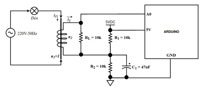
I have a digital filter circuit as shown below. First, I have successfully filtered low pass and high pass. But when I calculate the apparent wattage of the 15W - 220V bulb it fails again. Everyone please check if I calculated the Irms value correctly, why my apparent power output is very low about 1W.

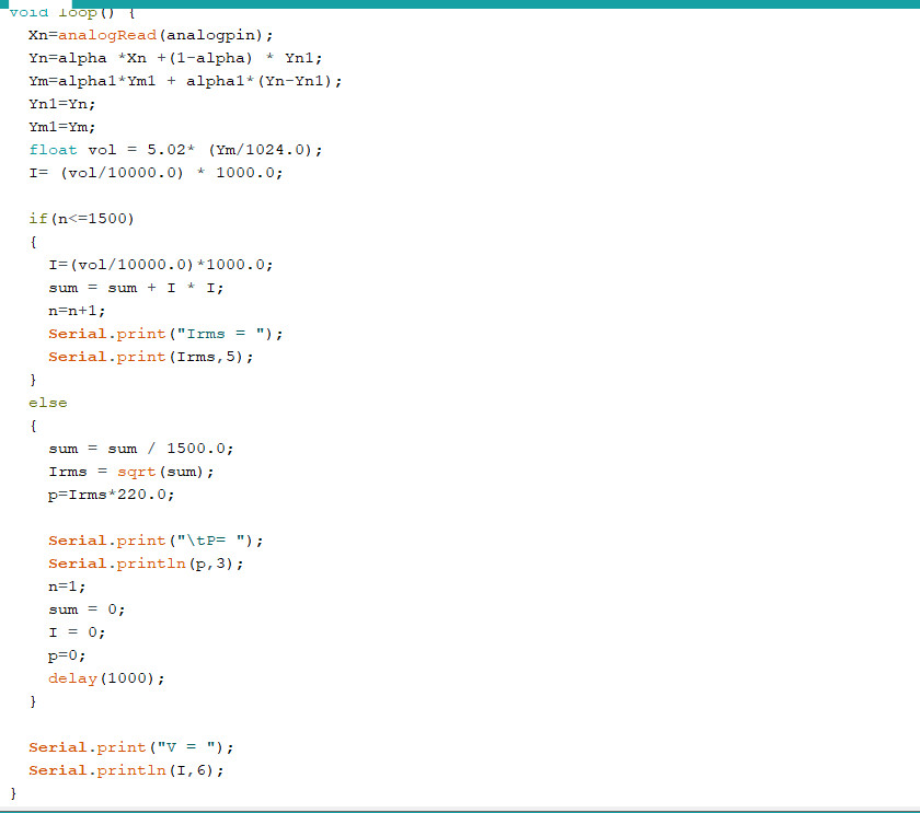
Post code, not pictures of code.
const int analogpin=A0;
int Xn=0;
float Yn=0;
float Yn1=0;
float alpha=0;
float dt=0.0002;
float Fc=50;

float Ym=0;
float Ym1=0;
float alpha1=0;
float dt1=0.00001;
float Fc1=10;
float I=0;
int n=1;
float sum=0;
float p = 0;
float Irms=0;
void setup() {
  // put your setup code here, to run once:
  Serial.begin(115200);
  float k=2*3.14*dt*Fc;
  alpha=k/(k+1);
  float k1=2*3.14*dt1*Fc1;
  alpha1 =1 /(k1+1);
}

void loop() {
  Xn=analogRead(analogpin);
  Yn=alpha *Xn +(1-alpha) * Yn1;
  Ym=alpha1*Ym1 + alpha1*(Yn-Yn1);
  Yn1=Yn;
  Ym1=Ym;
  float vol = 5.02* (Ym/1024.0);
  I= (vol/10000.0) * 1000.0;

  if(n<=1500)
  {
    I=(vol/10000.0)*1000.0;
    sum = sum + I * I;
    n=n+1;
    Serial.print("Irms = ");
    Serial.print(Irms,5);
  }
  else
  {
    sum = sum / 1500.0;
    Irms = sqrt(sum);
    p=Irms*220.0;

    Serial.print("\tP= ");
    Serial.println(p,3);
    n=1;
    sum = 0;
    I = 0;
    p=0;
    delay(1000);
  }

  Serial.print("V = ");
  Serial.println(I,6);
}
Have you verified that values of alpha etc are all correct?
Yes, I verified
Are you sure that the voltage at A0 is actually what you think it should be?
(post deleted by author)
Appears to be a duplicate?
Your two or more topics on the same or similar subject have been merged.
Please do not duplicate your questions as doing so wastes the time and effort of the volunteers trying to help you as they are then answering the same thing in different places.
Please create one topic only for your question and choose the forum category carefully. If you have multiple questions about the same project then please ask your questions in the one topic as the answers to one question provide useful context for the others, and also you won’t have to keep explaining your project repeatedly.
Repeated duplicate posting could result in a temporary or permanent ban from the forum.
Could you take a few moments to Learn How To Use The Forum
It will help you get the best out of the forum in the future.
Thank you.
I want to calculate Irms😐
But you're calculating it based on the voltage at A0.
If that voltage isn't doing what you think it is, then your calculations won't give the answer you expect.
What do you think the voltage at A0 should be doing?
Yes
That isn't an answer to my question!
Again: What do you think the voltage at A0 should be doing?
I think the voltage at A0 fluctuates around 0. From there I calculate the current and then deduce Irms
And is that valid as in input to the Arduino's ADC? ![]()
What do you think that the ADC will do with an input below zero?
2 Likes
No. The above code is that I have filtered low pass and high pass. So the voltage is now oscillating around 0 including both negative and positive. I want to calculate I rms because this is not a stable sine wave. Take a look at the circuit diagram that I sent above
I tried running but only Irms count is wrong. The previous part was fine
Again, is that valid as in input to the Arduino's ADC?
What do you think that the ADC will do with an input below zero?
I did:

But is it ?
In that circuit, I think not ... ![]()
Your circuit is OK but your code has quite a few problems.
Why not use the Arduino Current Transformer library
2 Likes