I have 2 analog signals that will be pulse waves. (They are sine waves input to the analog ports but the arduino does not read negative voltage so the input to the arduino's perspective is pulse waves).
I want to be able to calculate the phase delay between the 2 signals. the frequency of the input will be variable between 800hz-1khz and the time delay will be between 0-0.3ms.
since you said the input shouldn't see the negative values, have you considered capturing the timestamps of the first non-zero value and measuring the time between them (or the first sample > 0)?
the phase difference would depend on the period of the waveforms, the difference in timestamps between consecutive waveforms.
You need to block that negative voltage as it can damage the processor .
I would use a pair of comparators feeding digital inputs and count the time between switching .
You should be able to get phase and frequency from that .
Firstly I'd level shift to mid-rail (2.5V) so you get the entire signal waveform, this will reduce error in subsequent calculations. You can always compensate by subtracting the long term average voltage to get signed signal values.
With two sine waves you can simple compute the amplitude of the product of the waveforms and divide the product of the amplitudes of the original waveforms, giving the cosine of the phase difference. (You'll have to determine leading or lagging by some other means).
So long as this is summed over a whole number of cycles it should be very robust to noise etc, especially if you calculate rms amplitudes, not peak-to-peak - note there's a factor of sqrt(2) you may have to throw in to compensate for rms.
I would leave the signals as you have them (i.e. no negative) but add series resistance and a schottky diode to protect the processor. I would use a digital input instead of an analog input. The possibility of the digital thresholds will be a key to using a digital or not.
Which processor are you using?
For the time delay you will have to use one of the hardware timers. With a range of 0 to 0.3ms you will not be able to use millis().
For frequency you could use a timer or count multiple cycles using millis(). The number of cycles will be determined by the required accuracy.
We don't know how quickly the phase or frequency so I can't suggest the sequence of measurement.
@OP
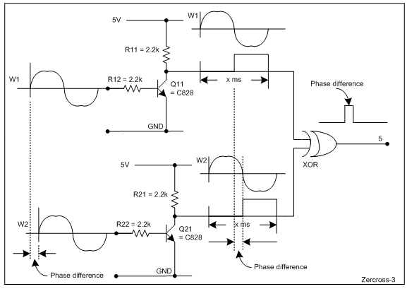
You may build the following circuit (Fig-1); where, the ON-period of the output signal of the XOR gate is proportional to the phase diffrenece between W1-W2. The value of the phase delay can be measured using pulseIn() function of Arduino UNO.