I want to measure the voltage of a LiFePo4 battery with an MCU by using a Voltage Divider Circuit with two 1 Million Ohms Resistors. Since the state of charge courve of this battery type is very flat, it should be as accurate as possible.
So I was beginning to measure the voltage of the battery with a multimeter first and noticed an issue: All my 3 multimeters (prices between 30 and 70 Euros) show different values between 3.21 and 3.35 Volts.
I have just found out that I can calibrate the multimeter by rotating a potientiometer on the backside, but I do not know which one measures correctly and what voltage source I can use to calibrate.
My question is: In the world of Arduinos and ESPs, is there a really accurate voltage reference that could be used to do a calibration?
I have various Arduino Nanos and Arduino MInis, many ESP32, S2 mini, S3 and C3
Does anyone here have a really expencive calibrated Multimeter who could tell me how accurate the LDOs of one of those MCUs are and if they can be used to calibrate my multimeters, so I can calibrate my ADC input of the voltage divider? Or is there a better accurate voltage source than the LDOs?
Just be aware that the 1 MOhm resistor far exceeds the suggested output impedance of a circuit connected to AVR based boards; the output resistance of your circuit should be below 10 kOhm accorcing to e.g. the 328P datasheet.
I've never bothered to lookup the specs of ESP based boards because I don't use them.
Hi @sterretje
the "suggested" impedance is to provide a time constant for the CR circuit made by the source impedance and the input capacitance of the ADC (14pF)
that will enable accurate conversions to take place on a signal that is changing rapidly.
1M - 14pf gives a time constant of 14us and a 5T period of 70uS. A battery voltage wont change much in that time.
Did you see I've measured the input resistance of an ADC (on a NANO) at over 400GOhm?
This has two outputs 2.048V and 4.096V, 0.1% accuracy.
You can use one of these to check the calibration of your multimeters.
If you connect either of the two outputs to the Analogue Reference input of an Arduino, and use analogReference(EXTERNAL) then your ADC will have convenient 2mV or 4mV sized steps.
Ah, but that's relative. The absolute output can vary a lot more between individual devices:
So relative stability will be fairly good, but as an absolute reference, it's not particularly useful.
See #9 for a more reasonable reference that's also conveniently accessible for any hobbyist.
Explain more, so I learn.
I was expecting that min-typ-max line on your image counting also load variations between zero and max. But it is for Iout=0mA, right?
Refer to the datasheet (http://www.advanced-monolithic.com/pdf/ds1117.pdf); I took the snippet from the table on page 2:
So this represents the variation in output voltage without load for this family of devices. I.e. one device may output 3.26V and the next one 3.34V and both will still be within spec. This is at the same temperature; the variations over the permissible temperature range are considerably larger (in bold; second line in the snippet I posted earlier), reflecting the inherent problem of temperature instability of absolute voltage references.
Actual regulation/stability under load is a different issue and addressed separately in the datasheet; you'll find that the absolute load regulation is actually quite good as expressed in a few examples in the table on page 4. However, those figures are under the assumption of stable junction temperature - which is virtually impossible to maintain (under varying load!) in a real-world system. Temperature stability is also addressed in the datasheet and should be taken into consideration; if you add all this up, you'll get to the approximation of 0.2% that you find on the device summary (first page). As you can see from the data on page 2, the load regulation of the device is in fact much better than the absolute stability of the output voltage. Hence my earlier remark.
There's the secondary issue of the "1117" as such being made by several manufacturers and absolute stability as well as load regulation can be expected to vary wildly between devices of the same generic type, but from different makers. However, you'll find that the AMS1117 specifically is one of the poor performers if you compare it to the variants from major Western makers (TI, ST, Onsemi) - on the other hand, there are likely '3rd party' Chinese-manufacture ('counterfeit', if you will) 1117 IC's out there that perform even worse than the AMS variant.
TL;DR - using a linear regulator as an absolute voltage reference is not a good idea if you need any form of absolute accuracy. Use an actual voltage reference and keep a close eye on stability data to suit the needs of your application. For calibrating DMM's, this is quite relevant since these are devices where you want/expect a reasonable degree of absolute correctness.
The measuring resistance of those cheapy DMMs may be less than the 20Mohm that is quite standard.
But even 20Mohm will influence the voltage divider of 1Mohm resistors by 5%...
Yes, ideed very interesting! I was thinking about building such a circit after reading the article but thinking about all the things I have on my list right now, I might buy a finished one using an AD584KH.
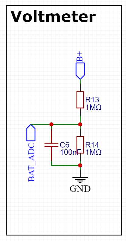
I've seen some people using 1M Ohms resistors with ESPs so the battery doesnt drain too fast. Most people report that this is fine as long as the voltage divider circuit uses a small capacitor, otherwise the readings are unreliable. On my PCB I have an 100nF capacitor and the measurment is very retest-reliable, but unfortunately not valid. It is off by about 0.1-0.2V
Will buy a similar one, thanks!
Unfortunately my PCB does not have space for more ICs, for now I want to focus on the software side my calibrating it in Arduino IDE, if I cannot mange to get a reliable measurment I will have to reevaluate
Part of your calibration issue is that the multimeters may drift with time and temperature after you’ve calibrated them .
You could always buy a decent multimeter.
My 19yr old fluke was checked against a calibrator and still within spec .
Whie the BAT_ADC is going to an ADC pin of the ESP32 and B+ is the battery positive
The code for measuring is this:
//VOLTMETER
float adc_calibrationOffset = -0.01;
float in_calibrationOffset = 0.180;

int BatteryADC = 5; // pin Voltage Divider Input
float adc_voltage = 0.000;
float adc_calibrated = 0.000;
float in_voltage = 0.000;
float adc_to_volt = 0.000;
float R1 = 1000000.000;
float R2 = 1000000.000;
// Integer for ADC value
float adc_value1 = 0.000;
float adc_value2 = 0.000;
float adc_value3 = 0.000;
float adc_value4 = 0.000;
float adc_value = 0.000;

void MeasureBattery() {
  delay(200);
  adc_value1 = analogRead(BatteryADC);
  delay(200);
  adc_value2 = analogRead(BatteryADC);
  delay(200);
  adc_value3 = analogRead(BatteryADC);
  delay(200);
  adc_value4 = analogRead(BatteryADC);
  delay(200);
  adc_value = (adc_value1 + adc_value2 + adc_value3 + adc_value4) / 4;
  adc_to_volt = adc_value * (3.300 / 4095);
  adc_calibrated = adc_to_volt + adc_calibrationOffset;                     // Calibrate with theoretical value from voltage divider calculator
  in_voltage = (adc_calibrated / (R2 / (R1 + R2))) + in_calibrationOffset;  // Calculate voltage at divider input and add another calibration value by double checking with multimeter
}
It should function like this:
First I measure the battery voltage (lets say I get 3.300V)
Now I measure the volts that is going into the ADC pin with a multimeter, lets say I get 1.550V.
I compare this number with the value that should go into the PIN if the resistors would have no tolerance (since the divider is 0.5, it should be 1.650V)
This shows me that the divider circuit is off by 0.100V in that theoretic example.
Now to the software side: I measure the mean of 4 measurments and attain "adc_value", which is then calculated to volts with adc_to_volt = adc_value * (3.300 / 4095);
now I make the first calibration: I add the variable adc_calibrationOffset so the ESP32's measured ADC input "adc_to_volt" is matching the multimeter's value of the supposed pin's input
now I should have an accurate measurment by the ESP32, but still, the tolerance of the resistors is not taken into account, so another calibration is necessary. So first, I calculate the battery voltage in regards to the voltage divider with this: in_voltage = (adc_calibrated / (R2 / (R1 + R2))) + in_calibrationOffset; and add the variable in_calibrationOffset which is the difference between the real battery measurment (3.300V) and value I would attain with in_voltage
I would be very happy for any advice how to make it more accurate on the software side. For the hardware measurments I'm still waiting for a new multimeter and the reference voltage device.
Hi,
What is your DMM?
Have you allowed for its load impedance across the 1M resistors causing the divider to load differently when the DMM is connected.
What happens when you use 10K resistors instead of 1M?