Calibrating Heidenhain encoder with arduino

Hi, I need some help with my project. I have some basics in electronics but I'm almost a complete beginner in programming. My workflow is as follows. I found a similar project and tried to modify it to suit my needs. However, I have encountered problems where I am stuck and don't know how to proceed.

Short introduction. I am making an auxiliary device for calibrating the Heindenhain encoder. This encoder is located on the rotor of the electric motor. My company fixes the motor winding and always moves the encoder in question during maintenance. As a result, when the motor is returned to the customer and he connects it for use, the motor starts to overheat. The employees have tried to mark the original position of the encoder with a marker, but this is very inaccurate and not always correct. It is unprofitable for me to take each motor to another company where they can calibrate it. And buying a test system is unprofitable as it would not pay for itself. That's why I wanted to do it with an Arduino.

The first thing I did was visit an authorised service for these encoders to see how they set them up.

Sensor used: ERN 1387
Datasheet: https://www.heidenhain.be/fileadmin/pdb/media/img/1085677_03_A_02_ExN_13xx_Aufzugtechnik_en.pdf
(page 5)

The technician at the authorised company found the zero point at the reset point and reseted the position in their program.
Screenshot_4

He tightened and fixed the encoder. The test continued.

On the rotor of the motor in question, there are 3 magnets that create 3 poles. 0°, 120°, 240°. He turned the rotor manually (motor isnt connected to voltage) . Let's say we went from 0° to 20°. He then applied 24V and 1/10th of the current to the motor according to the motor's rating plate.

Screenshot_3

The rotor returned to the nearest pole. So from 20° back to 0°. However, it was not exactly 0°, but about 1.53°. The technician said that 3° was the maximum tolerance. Well, the whole test is to come back within three degrees.

So I started to make a simple homemade version. If the outputs of the encoder are A, B, R, C, D. And I know that 2048 pulses should be per full revolution I thought it could be done via attachInterrupt() and a couple of conditions. Where when it detects a pulse from R it knows it's at 0, so I know where to start.

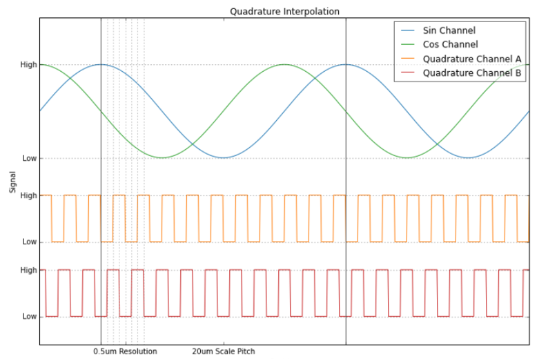
I found an existing project on the internet:
http://www.everythingbends.com/2015/03/encoder-interpolation.html

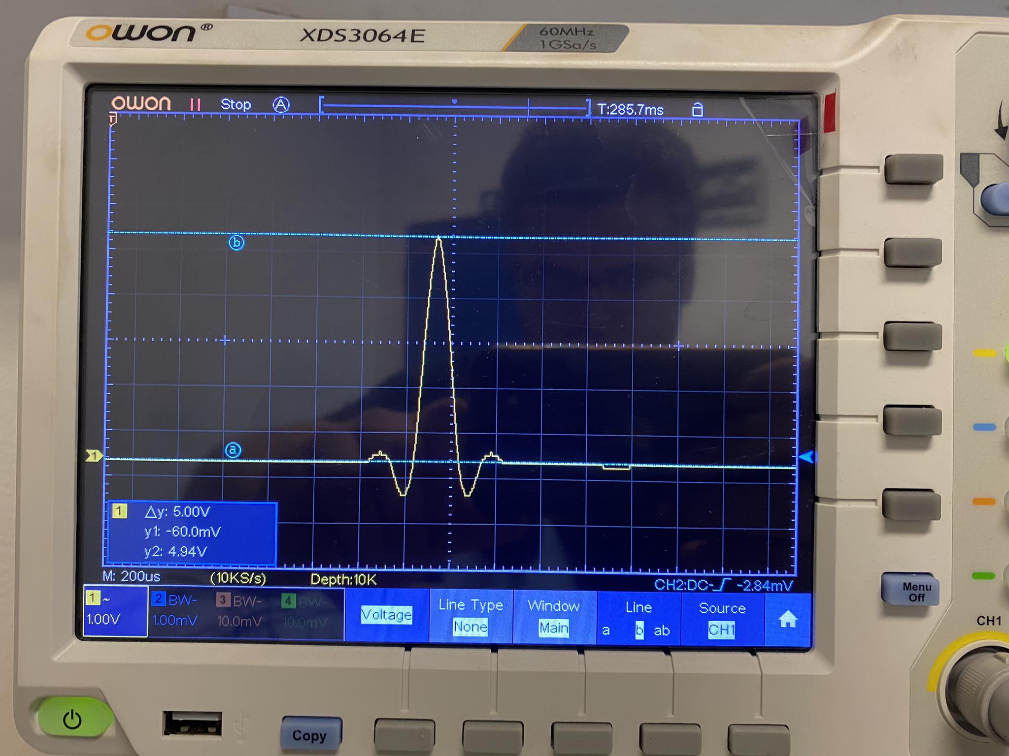
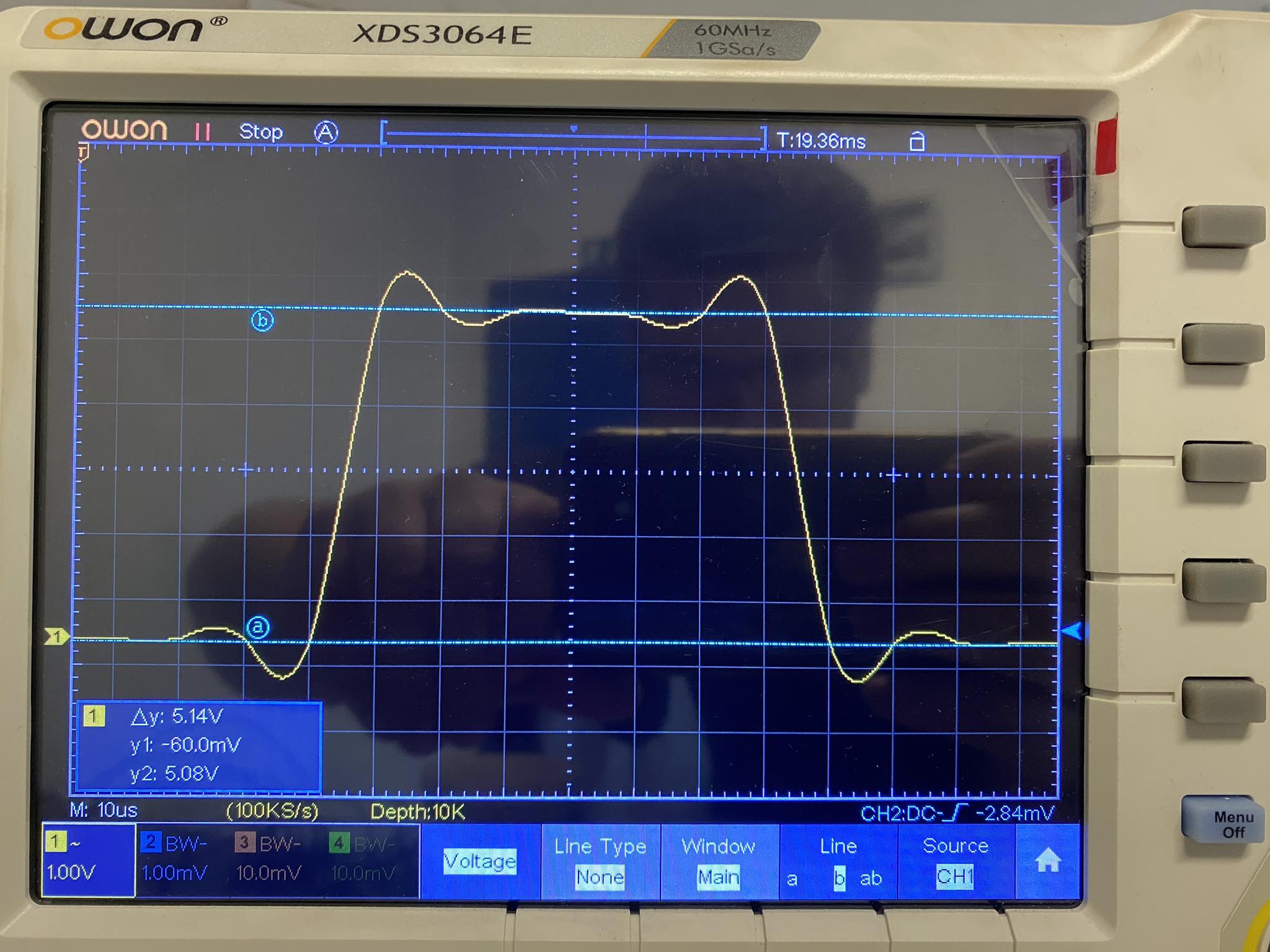
I repeated the conversion from sin/cos to TTL and started calculating with the arduino

I bought a ready-made evaluation board to avoid problems with soldering etc.


https://www.ichaus.de/upload/pdf/NV_NVH_datasheet_E1en.pdf

So I converted A, B, R on the output and calculated A and B with such a program. So far I have done this on an Arduino Uno. I plan to switch to DUE as I need another attachInterrupt().

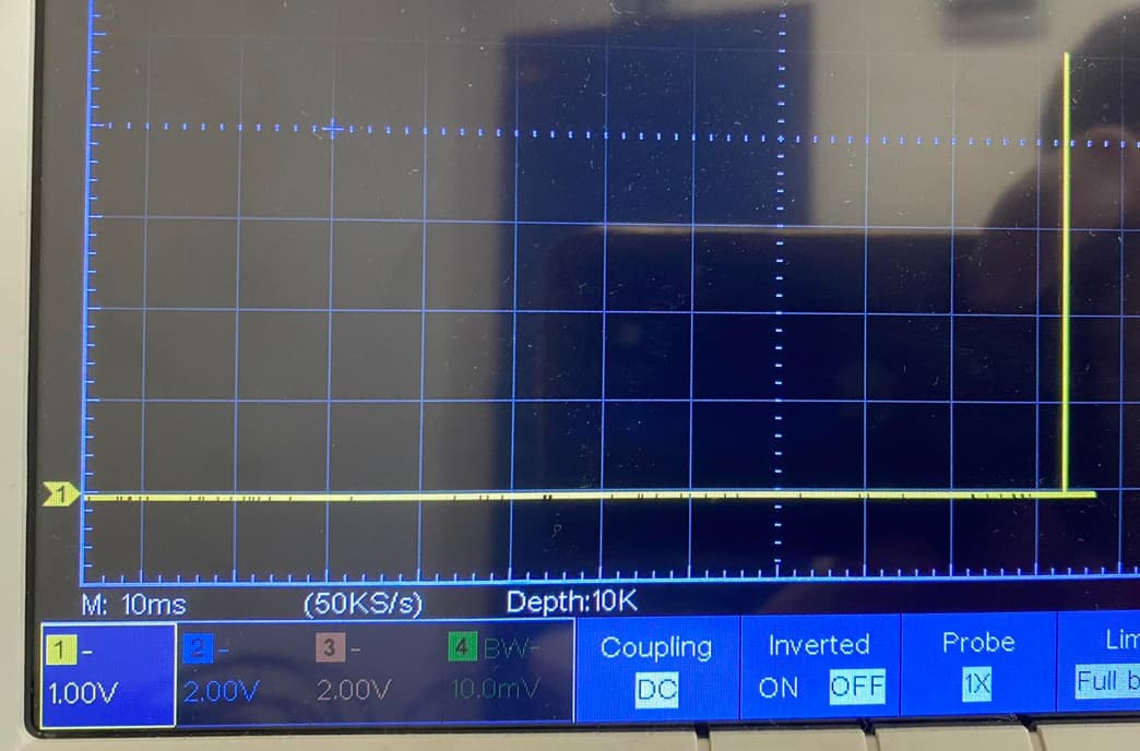
My current problem is that I can't get a pulse from R. As soon as I attach it, it starts counting something even without spinning the encoder.

#include "U8glib.h"
#define pot A0 
#define pwm 5
#define CLK 13
#define MOSI 11
#define RES 10
#define DC 9
#define CS 8

U8GLIB_SH1106_128X64 oled(CLK, MOSI, CS, DC, RES);

long int prepis = 0;
volatile long temp, counter = 0;
void setup(void) {
  pinMode(2, INPUT_PULLUP);  
  pinMode(3, INPUT_PULLUP);  
  attachInterrupt(0, ai0, RISING);
  attachInterrupt(1, ai1, RISING);	
  Serial.begin(9600);			
  // oled.setRot180();
}

void loop(void) {


    if( counter != temp )
  {
    Serial.println (counter);
    Serial.println (temp);
    
    temp = counter;
  }
  // porovnání uloženého a aktuálního času při rozdílu větším než 100 ms se provede obnovení displeje, čas můžeme nastavit dle potřeby
    oled.firstPage();
    do {
      // funkce vykresli vykreslí žádanou obsah
      vykresli();
    } while ( oled.nextPage() );
    // uložení posledního času obnovení
  

}
void ai0() {
  if(digitalRead(3)==LOW){
    counter++;
    }
      else
        {
          counter--;
        }
    }
  
  void ai1() {
    if(digitalRead(2)==LOW){
      counter--;
      }
        else
      {
        counter++;
      }
  }


void vykresli(void) {
  

  oled.setFont(u8g_font_unifont);
  oled.setPrintPos(0, 10);
  oled.print("pocet impulzov");
  oled.setPrintPos(0, 30);
  oled.print(counter);
  oled.setPrintPos(0, 45);
  oled.print("poloha v stupnoch");
  oled.setPrintPos(0, 60);
  oled.print(counter/5.6888);

}

Arduino Micro or Pro Micro might be more convenient. It has 5 external interrupt pins, and is small enough to fit on the prototype area of that board you posted a photo of.

But more interrupts are also possible on your Uno, using "Pin Change Interrupts". These are not quite as fast or flexible as external interrupt pins, but might be good enough.

I think we need to see a schematic. Hand drawn is ok.

How did you connect R? How did you attach A, B? Your code does not indicate which arduino pins have been assigned which functions. Does the sketch you posted contain any code to deal with R's signals?

I would recommend you upgrade your code to use U8G2, because U8G has now been replaced. It will be easy if you do it sooner rather than later.

Also please click Auto-Format before you post your code again.

Thanks for the response Sir, I bought the DUE first then when I heard about the problems with the I2C bus I bought the UNO. Since I have enough space, I don't mind if the Arduino test board is bigger.

The code I posted at the beginning is just what I use with A, B, which I get from the board where I convert sin/cos to TTL. I simply connect this to digital input 2 (A=digital 2) and 3(B). However, as I'm new to this and don't want to mix R with A and B in the existing program, I simply try to count R separately. I simply connect this to digital 3. The board used is an Arduino Due.

 volatile int state = 0;

void setup(){
  Serial.begin(9600);
  pinMode(3, INPUT);
  attachInterrupt(3, state_change, RISING);

}

void loop(){
 
  Serial.println(state);
  delay(1);
}

void state_change(){
  //state = (state + 1);
  if(digitalRead(3)==HIGH){
    state++;
    }
      else
        {
        }
    }


//}

I am sending a photo from an oscilloscope of what R looks like after the conversion.

The original R looked like this.
Screenshot_8

Could the shape of the R cause a problem?
I don't see any button "auto-format"

for measuring time between pulses I have used both a Due and an ESP32
for example, see read-time-between-rise-on-3-separate-input-pins

I am going to assume that in this program, pin 3 is the pin you have attached to the R pin.
If so, you may just be picking up random glitches. We don't have a diagram to be able to tell if you have an external pull-up resistor on that input.

I suggest you post a diagram of exactly how you have set up your circuit.

You could also try INPUT_PULLUP instead of just INPUT

I have a 10k ohm resistor and have tried "INPUT_PULLUP" but there is no change.

Whats program where you can place arduino and wires online? I will do schematic when I come home from work.

Hi, @medvih

Can you please post a copy of your circuit, a hand drawn circuit in jpg, png?
Hand drawn and photographed is perfectly acceptable.
Please include ALL hardware, power supplies, component names and pin labels.

Hand drawn at this stage is faster and does not require a steep learning curve.

Thanks.. Tom... :smiley: :+1: :coffee: :australia:

Hi,
Thanks for the diagram.

Can you post images of what you are getting from A and B outputs.
It looks like the conversion is into "quadrature" encoder signal.

Where A and B are 90deg out of phase, the direction of rotation is determined by the direction of the phase difference.
The R output is a syncing pulse, usually once in each encoder revolution.

image

Tom... :smiley: :+1: :coffee: :australia:

Looking at the diagram above, R4 (10k) connection does not make sense to me. You might be better off omitting it altogether just like for A and B and using INPUT_PULLUP on D4, without the resistor (unless that's what you had already tried).

The duration of the R pulse seems very short, from what I can see from the oscilloscope photo. It shows you are at 10 ms. Are you able to make the time base faster and actually measure the duration of the R pulse?

I am sending a picture from oscilloscope. A is yellow, B is blue and R is orange.

Thank you for your reply. I have done a better job of displaying the R. Is it enough to just measure it like this with the cursors?


Thanks for posting the scope images. Very helpful. The measurement with cursors is what is needed and tells us that the R pulse is of a reasonable duration (2.78 ms).

I went back and looked at the circuit diagram and then also at the data sheets for the icHaus and for the ERN1387.

I think there may be a problem with the connections.
If I understand it correctly, the encoder itself generates an R pulse.

So, a couple of questions for you:

  1. Are the scope measurements of the R pulse taken from the encoder itself or from the output of the icHaus?
  2. Are you connecting the Z output on the icHaus (called R in your circuit diagram) to the Arduino input?

I think the problem may be that you have mis-connected the signals. I believe the 1387 sends sin/cos signals to the icHaus chip, which it converts A and B quadrature signals with the resolution set by that chip.
The icHaus the synthesizes a Z output from the sin/cos signals coming into the PCOS/PSIN etc pins. It cannot take the R signal from the 1387 encoder.

If you look at p4 of the icHaus data sheet, it shows:
PZERO Index Signal Enable Input +

I think you can get the rotation mark one of two ways:

Either directly from the encoder R+ to the Arduino input. Please double check the voltage of the R pulse. I could not see the scale for voltage on the orange trace.

Or, use the synthesized Z output from the icHaus. To get this output, you'll need to look at table 5 on p10: the ROT pin should be high or low, but not open.
And p12 says that the Z output must be enabled at differential inputs PZERO and NZERO. Table 9 on this page shows where in the rotation the Z output will change.

It may be more straightforward to connect the R output from the encoder directly to the Arduino, provided the voltage is OK, etc. And the A and B outputs would be from the icHaus.

1 Like

yes, it should look like this
Screenshot_8

picture in post #13 is from output of icHaus

I'm trying to count pulses from R(Z from icHause)

I think I understand what you're trying to explain. The PZERO and NZERO inputs do not do the same thing as the PSIN and NSIN pins...they are not designed to convert R+ and R- from the encoder. I thought that if zero was in the name, you had to connect the reset pulse from the encoder directly.

I started with the easy way. I am sending pictures of what the R+ and R- output looks like directly from the encoder. So should I try to connect it to the Analog input and try to read something via analogRead() ?


I don't think that will work. The signal is quite ragged and you won't know what value to choose for a +ve result.
And thanks for measuring the voltage: this is a surprising result. It is only ~500 mV. I was expecting it to be ~5V, assuming you are powering the encoder with 5V. This small change likely won't be enough to trigger an interrupt, or be readable as a digital HIGH value either.

You posted a picture in post #16 of the expected signal wave forms. Where is that picture from?
Looking at it, it shows that there is an alternate signal shape for R, shown with a dotted line. That signal appears to have clear and sharp edges, and may be better suited to connecting to the Arduino, etc. Unfortunately, that picture only shows a 0 reference for R, but does not show what the actual voltages are.

So, perhaps back to using the Z output from the icHaus. I think you could try connecting PZERO to 5V and NZERO to GND, and see what you get on the scope. Connect the ROT pin to HIGH or GND as per the table.
Do not connect R from the encoder to the icHaus.

I suspect that this will work.

I am powering encoder with 5V.

Thats from official datasheet. https://www.heidenhain.com/fileadmin/pdf/en/01_Products/Prospekte/PR_Rotary_Encoders_ID349529_en.pdf

Osciliskop shows nothing. Literally 0V.

But I realised that I had the ROT connected to ground all the time. I actually bought their test board from icHaus (https://www.ichaus.de/upload/pdf/NV_NVH_datasheet_E1en.pdf page 20).

I connected R+ to PZERO, R- to NZERO and was watching Output from icHaus. . I don't know why it has a different shape, before I saw it as a square signal...see post #13, but it already has 5V. The second picture is the same output but I changed the ROT switch.


Hi,
Are you using a x10 probe?
If so, have you compensated it?

Tom.. :smiley: :+1: :coffee: :australia:

No x1