Hello there im trying to learn how to program the arduino and i would like to make a project with lots of leds that are tied each one directly on the outputs of the arduino mega using a resistor before starting learning about shift registers.
specifically i want to put 50 leds on the arduino and code it to scan them in patterns and stuff
each pin of the arduino will have only one led on it with a current limiting resistor which will only allow 20ma of current to pass.
if i just scan them and toggle each one at a time on and off there wont be any problems i suppose
but what will happen if i code it to scan all the leds and keep them turned on simultaneous or if i code it to just turn on all the leds together for 3-5 seconds?
will the arduino handle 20ma*50output pins = 1amp total simultaneous current draw from 50 of its outputs together?
or it will blow up in my face?
(i know i should probably use a shift register, a led driver or something but right now im only interested to learn if what i said is possible and if the arduino can handle it. when i complete this project ill start learning about shift registers and stuff)
will the arduino handle 20ma*50output pins = 1amp total simultaneous current draw from 50 of its outputs together?
No.
or it will blow up in my face?
Well not so much explode but it might melt inside.
I am assuming you have a Mega so see section 38 of the data sheet. There is a 200mA limit on the power pin, this sources the power provided by the I/O pins. There are four of these so you might think the limit is 800mA, but this is a bit controversial.
However in addition it says:-
Although each I/O port can source more than the test conditions (20mA at VCC = 5V, 10mA at VCC = 3V) under steady state conditions (non-transient), the following must be observed:
1)The sum of all IOH, for ports J0-J7, G2, A0-A7 should not exceed 200 mA.
2)The sum of all IOH, for ports C0-C7, G0-G1, D0-D7, L0-L7 should not exceed 200 mA.
3)The sum of all IOH, for ports G3-G4, B0-B7, H0-H7 should not exceed 200 mA.
4)The sum of all IOH, for ports E0-E7, G5 should not exceed 100 mA.
5)The sum of all IOH, for ports F0-F7, K0-K7 should not exceed 100 mA.
I am assuming you have a Mega so see section 38 of the data sheet. There is a 200mA limit on the power pin.
In addition it says:-
Although each I/O port can source more than the test conditions (20mA at VCC = 5V, 10mA at VCC = 3V) under steady state conditions (non-transient), the following must be observed:
ATmega1281/2561:
1)The sum of all IOH, for ports A0-A7, G2, C4-C7 should not exceed 100 mA.
2)The sum of all IOH, for ports C0-C3, G0-G1, D0-D7 should not exceed 100 mA. 3)The sum of all IOH, for ports G3-G5, B0-B7, E0-E7 should not exceed 100 mA. 4)The sum of all IOH, for ports F0-F7 should not exceed 100 mA. ATmega640/1280/2560:
1)The sum of all IOH, for ports J0-J7, G2, A0-A7 should not exceed 200 mA.
2)The sum of all IOH, for ports C0-C7, G0-G1, D0-D7, L0-L7 should not exceed 200 mA.
damn thats what i thought so, i had totally forgot about any current limitations besides the 40ma absolut max on every pin when i did all the programming.
its my first arduino and my first try at programming it, the arduino i bought hasnt yet arrived but i did started to write the code and i was checking it on the simulator.
the truth is that i did a lot of hard work trying to make this code work if you consider that i've never written code before so i cant just delete all this code i wrote and start coding from scratch considering that the new code is going to operate some other device like a shift register instead of a led because it is just too difficult for me at this point and i dont have a clue on how a shift register works...
in order to keep my code the same and not change anything on it, what i need is a device in each output pin of the microcontroller which will take all the current weight from the microcontroller.
im guessing i transistor acting as a switch that will connect each led at an external +5v supply whenever an output is set to HIGH will do just fine but then i will need 50 transistors and some resistors so it will be a mess....
so i have to ask.... : is there any magical chip with lots of inputs-outputs that is able to do exactly what i said without the need to change my code?
(a chip that when it takes the +5v signal of each microcontroller's output pin it will supply the proper led with the current that is needed without overloading the microcontroller)
All you'd be replacing is a call to digitalWrite(). If your sketch involves any complex logic to decide where/when to turn the outputs on and off, that needn't be affected. On the other hand, if all it's doing is turning a sequence outputs on and off, you'll quickly come to realise that, although this might represent a big step up your learning curve, it is not especially difficult in the scheme of things and not something that you need to put on a pedestal.
If you really want to run the code as-is without exceeding the Arduino's current limit, one option is to use much bigger current limiting resistors to keep the overall current within the limits that the Arduino can tolerate. The LEDs will be correspondingly less bright, but they'll still be visible.
Yes it can. Just need to limit the current.
Mega has 4 VCC pins, 200mA per pin as I have documented from Atmel directly in the past, so total current can be up to 800mA.
Have to pay attention to individual port current.
With super bright LEDs these days, don't need full 20mA per LED to be blindingly bright.
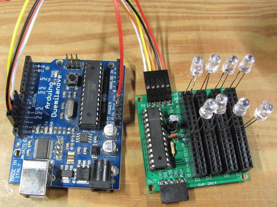
Next option: MAX7219, can control 64 LEDs. I have this little breakout board to make it easy to connect up LEDs. One current limit resistor sets the max current for all LEDs, 15 levels of brightness available. Purchase details & a video on the website. http://www.crossroadsfencing.com/BobuinoRev17/