Hi All, I am currently working on fixing/completely remaking the motherboard of a telescope mount, and I am running into trouble with the encoders that are mounted on the motors.
Here's a diagram of how I am hooking it up to my Arduino
So far with that setup, I have not gotten any good results. I have used this code:
#define ENCA 2 // pin2 of the Arduino
#define ENCB 3 // Pin3 of the Arduino
int ENCA_DATA;
int ENCB_DATA;

void setup() {
  Serial.begin(9600); // Activates Serial communication
  pinMode(ENCA,INPUT); // sets pin2 as the input
  pinMode(ENCB,INPUT); // sets pin3 as the input
}

void loop() {
  ENCA_DATA = digitalRead(ENCA);
// We simply read Pin2 of the Arduino and store the result in variable ENCA_DATA
  ENCB_DATA = digitalRead(ENCB);
// We simply read Pin3 of the Arduino and store the result in variable b
  Serial.print(ENCA_DATA*5);
  Serial.print(" ");
  Serial.print(ENCB_DATA*5);
  Serial.println();
}
And I get this output in the serial monitor when the +5v is connected
23:18:10.606 -> 5 5
and when its not connected
23:18:10.606 -> 0 0
This leads me to believe that the the pins I labeled 3 and 5 of the encoders are always high
another thing I have found interesting is that when I look at the back of the pcb the encoder is mounted on, I see 5 solder points underneath the encoder, but whenever I see images of components that look like the one on the pcb, There are only 4 pins, Am I just doing all this for the wrong component? Thanks a ton for any help you can give me!
You should provide details for the encoder you are using (part number, datasheet) or a link to the web site where you got it from. If all we can see is what you did on the basis of what you understood, we are not going to be able to diagnose what the problem may be.
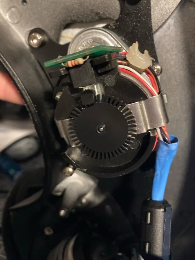
There isn't a part number on this, at least not one that gave any results, there is a string of characters but a google search doesn't return anything, I will post that when I have a chance. This is what the encoder looks like though.
That encoder looks like it is only a quadrature encoder and so will only give you a relative measure of the movement, so for your scope it will have to be calibrated every time it is switched on.
Basically you have two on/off signals that are 90 degrees out of phase. So the first thing to check is if you actually see this when you very slowly turn the motor.
Print out what the state of these two signals are when either one changes. Then you can tell if it works or you have not wired it up correctly.
You can also check these signals with a voltmeter.
Once you get the right signal then you will know what to look for, if not post your results and ask again.