I am a newbie to Arduino. I have watched the first 20 tutorials on youtube from Programming Electronics Academy, which are very good, but I still haven't found the answer to my question.
Can I use configure an Arduino Uno or 101 to output a voltage signal that's based on but not equal to an input voltage signal?
For example, I'll have a sensor that sends the Arduino a signal somewhere between 0-5 volts. Let's say it's 3.0 volts right now. At the moment the input is 3.0 volts, I want it to send an output voltage of say 2.8 volts. I'll need to do this over an entire range i.e. sometimes 4 volts, will come in and I'll need to send out 4.2 or whatever, but all in that zero to five range.
Measuring 0-5volt shouldn't be a problem, but most Arduinos don't have a D/A.
You could make a DC voltage from a PWM signal with a lowpass filter.
Parts will depend on what you want to drive/control.
Tell us what you want to do with this voltage.
Leo..
Leo, thanks for the response. Im not sure what D/A is.
All I want to do with this voltage is send it to another control module. What I want to do with the Arduino is use it to intercept the signal and modify it before it gets to the other control module. The signal comes from a temperature sensor on a portable diesel generator (like what you fire up in power outages). The signal sends a given voltage based on temperature. Say 70F=3 volts, I want to make it think it's 60F so I want to send 2.5 volts, or whatever, but in that range.
Read an analog input, then write your modified value out with a PWM pin (3,5,6,9,10,11 on an Uno) with a 10K and 4.7uF lowpass filter to feed the next device. http://sim.okawa-denshi.jp/en/CRlowkeisan.htm
void loop(){
potValue = analogRead(potPin) >>2; // read and divide by 4 to get 0-255 result
manipulatedValue = potValue - 100; // or whatever you're gonna do. 100 * .00488 = ~ 0.5V
analogWrite (pwmPin, manipulatedValue);
//
}
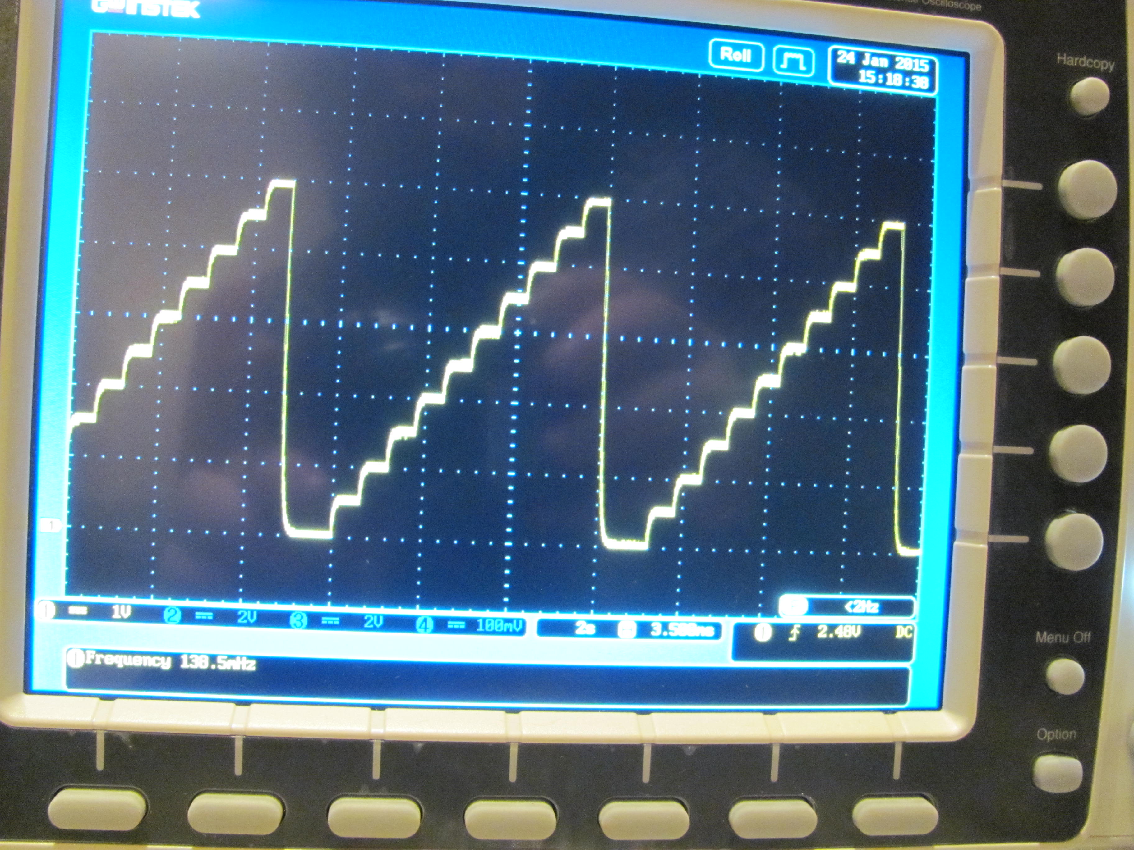
Attached pic shows analogWrite thru the same filter in steps of 25.
A/D is analogue to digital. D/A is digital to analogue.
If you always want to lower the signal voltage, then a 2-resistor voltage divider might be enough.
If you want to raise and/or lower the voltage, then a smarter system (like an Arduino) is needed.
Do you know the voltage range and input impedance of the receiving unit.
Without that, it will be harder to suggest a solution.
Leo..
CrossRoads:
Read an analog input, then write your modified value out with a PWM pin (3,5,6,9,10,11 on an Uno) with a 10K and 4.7uF lowpass filter to feed the next device.
That makes perfect sense to me, except I am not clear on why I would need the resistor and filter. Can't PWM send out the right signal on its own?
No, PWM only outputs a square wave 0/5V signal at 490 or 980 Hz, with the width of the high signal being 0/255 of the period (full off) up to 255/255 (full on) of the period.
Wawa:
If you always want to lower the signal voltage, then a 2-resistor voltage divider might be enough.
Nope, sometimes, but not often I will want to raise the voltage slightly. Furthermore, the voltage change won't be constant. I'll want to vary it different amounts under different conditions.
Wawa:
If you want to raise and/or lower the voltage, then a smarter system (like an Arduino) is needed.
What do you mean "like an Arduino"? Do you mean something more powerful than an Arduino?
Wawa:
Do you know the voltage range and input impedance of the receiving unit.
Without that, it will be harder to suggest a solution.
Leo..
The receiving unit just isn't in question here. As long as the signal is within the voltage range specificed and at or near 10ma, it will work. The problem is I'm not 100% sure the Arduino can alter the signal in the way I need it too. If it can't I'll have to find another device. Any suggestions?
CrossRoads:
No, PWM only outputs a square wave 0/5V signal at 490 or 980 Hz, with the width of the high signal being 0/255 of the period (full off) up to 255/255 (full on) of the period.
Hmm, can it send an analog signal? It looks to me like it can. If not I'll probably go with the resistor and filter option if you think that will work and allow me to have a 0-5 volt output.
Robert1985:
What do you mean "like an Arduino"? Do you mean something more powerful than an Arduino?
The receiving unit just isn't in question here. As long as the signal is within the voltage range specificed and at or near 10ma, it will work. The problem is I'm not 100% sure the Arduino can alter the signal in the way I need it too. If it can't I'll have to find another device. Any suggestions?
An simple opamp with a pot could also do that. Drop/halve the input voltage with a divider, and amplify it to whatever you need. A micro could do that based on some manual or other input. Lin, log, delayed, whatever.
Any basic Arduino could do what you're asking, even a $2 Nano.
A simple RC circuit (10k+4.7uF)to turn PWM into DC, as CrossRoads suggested, can't be "loaded". It needs buffering. The solution could be an opamp voltage follower.
Leo..
Thanks! I want to say that you guys are really really helpful. I'll buy an Arduino and start playing with it to learn as much as I can. I don't know if I'll be able to do this whole project myself, but I plan to try so I can learn enough to understand it.
Oh, and I am going to want to control this via bluetooth, so I am thinking about going with the Arduino 101. What do you think?
"can it be programmed to do this based on an input voltage?"
Yes. Filtered output, Digital to Analog Converter (DAC), digitally controlled pot as voltage divider.
10mA drive, I'd go with a DAC with voltage output:
This thread you referenced http://www.toptechboy.com/arduino/lesson-8-writing-analog-voltages-in-arduino/
only makes LEDs look brighter or dimmer. Your eye can't see the square wave being applied. If you looked with an oscilloscope you would see the square wave. You asked for an output voltage based on input voltage, not a square wave output. Hence my suggestion for filtering, to smooth the square wave into a DC level as the scope shot pictured, or to use a DAC with 10-20mA drive output capability as suggested.
lol, for you it is, and probably for others here. From my perspective, it's the hard part because I already know how to do everything else on the project, but the software side is totally new to me.
Wawa:
Play with some of the examples that come with the IDE, and you soon will be able to write a simple program yourself.
That's exactly what I plan to do. Ultimately I am going to pay someone else to make the sketches, but first I need to be able to do it myself, and understand the process so I can communicate and oversee the work in an effective manner.
Wawa:
A digital pot has the same problem as an RC filter. You can't load it.
If you do, then the voltage will collapse.
Leo..
A voltage collapse at 10ma? I'll watch for that. If I have to do it another way I will, I'm super serious about this project.
CrossRoads:
This thread you referenced Lesson 8: Writing Analog Voltages in Arduino | Technology Tutorials
only makes LEDs look brighter or dimmer. Your eye can't see the square wave being applied. If you looked with an oscilloscope you would see the square wave. You asked for an output voltage based on input voltage, not a square wave output. Hence my suggestion for filtering, to smooth the square wave into a DC level as the scope shot pictured, or to use a DAC with 10-20mA drive output capability as suggested.
Good points, I'll go with the DAC. I'm ordering this stuff tomorrow, so I'll be playing with it over the next month or so.