can someone kindly explain whether this will work and why? new in Arduino
I want to be able to run a LED 12v push-ON push-OFF latching button switch connecting to Arduino Uno R3 that controls a HS-485 HB servo motor to turn and stop. Someone suggested a 9V regulator to take the power source of a 12V battery to feed into Arduino - I get this because Arduino Uno R3 can accept input from 7v-12v.
What I don't get is whether the 12V Push-On and Push again OFF switch will work with Arduino. The suggested method is as follows:
(1) Connect a 221 ohm resistor + leg to Push button - leg on a mini breadboard,
(2) Connect the negative leg of 221 ohm resistor to - rail on the mini breadboard,
(3) Connect the Push button switch + to any pin from 9 to 13 of Arduino Uno R3 +
So that Push button will link between Arduino and resistor.
My Questions -
why 221 ohm 1/4w +1%? would 220 ohm work? what is the electric theory behind it? why not 220K ohm? would 221 ohm 1/4w +5% work also? I see the 5% is much cheaper than the 1+ resistor.
I know it's not the answer to your question, but could you tell us where you got the 'suggested method' from? As it stands 221 ohm is a very precise value - did they mean 220 ohm, the final digit indicating the number of zeros?
Presumably they're using the (common) notation for resistor values that's used when marking SMD parts.
221 == 22 * 10^1 = 220
A resistor is not polarized, there is no positive or negative pin. Once you put it into a design, you may end up with one side of the resistor always being at a lower or higher voltage than the other - but that's up to your design. I realize you may know this and be using those terms to try to clarify a description of your connections; this is why a schematic (even photo of hand-drawn one - not fritzing diagrams though, we hate those here) is so much better than words for describing wiring.
Great, thx I will buy 220 ohm instead. I see 10k ohm for sale a lot, can I use 10k ohm to make the up to 12v led button work?
V=IR
So, I=5v divide by 220= 0.0227 amp
I guess 5/10k will be producing too small a current to make the led button to work? Yes? Or no? Just my guess
First the resistors are 220 ohm as was already suggested. It doesn't matter here but good to know for the future.
Lets take it one step at a time:
The LED's:
The UNO outputs 5V on the I/O pins. If the LED has a 2V drop (guess, I don't know the specifics of your LED) then you have about (5-2) /220 = 0.013 A or 13 ma. Probable a good place to start.
If all 5 LED are powered then the UNO will be outputting 5*13 = 68 ma
Switches:
If you enable the internal pull up currents for the switch inputs you don't need any resistor. The internal pullups are designed to be switched to ground.
Total power:
Reference this thread UNO Idle Power which suggests the UNO board with nothing attached required 80 ma. (seems high but I haven't used a UNO)
I don't recall the exact pullup current but lets assume they are 0.2 ma, so for 5 the total current is 1.0ma
So lets assume the total current draw is 160 ma (adding in some safety margin).
If you used 12V right to the board, the UNO on board regulator would dissipate (12-5)*0.160 = 1.12 watts.
If you stay with the 9V input the UNO on board regulator will dissipate (9-5)*0.160 = 0.64 watts
This post Power dissipation suggests the regulator could handle 1.5 watts. So I suggest you must stay with the 9V input
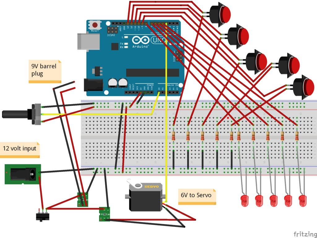
Now for the Grounds:
The ground of the POT should to to the Gnd on the top of the board. If left where it is you will get electrical noise from the power circuits.
The two vertical wires (black and red) should be removed. Ground from your power supply already goes to the board via the barrel plug.
I don't know the details about your voltage boards and what appears to be a TO-220 something with no ground. Be sure the input and output ground is the same for the voltage boards. Keep the power grounds close together then run to the barrel plug (which you have once you remove the two vertical wires).
Wow, thanks for the detail explanation!!!!
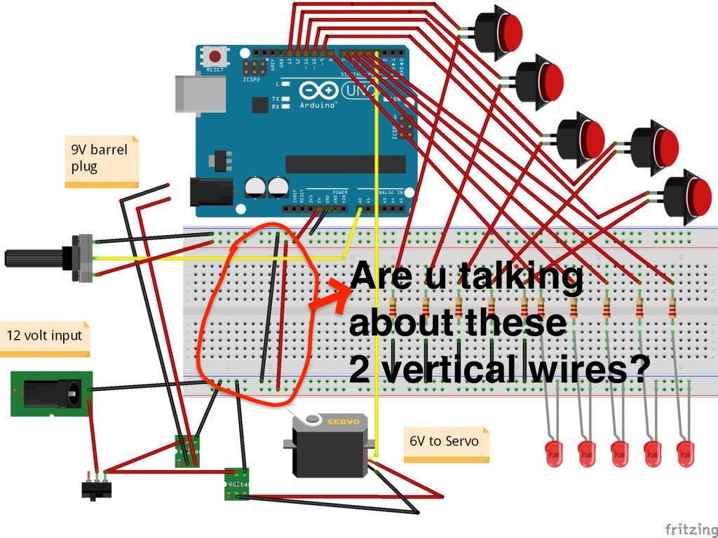
2 vertical wires - are they these circled in RED in my pic?
JohnRob:
HI,
First the resistors are 220 ohm as was already suggested. It doesn't matter here but good to know for the future.
Lets take it one step at a time:
The LED's:
The UNO outputs 5V on the I/O pins. If the LED has a 2V drop (guess, I don't know the specifics of your LED) then you have about (5-2) /220 = 0.013 A or 13 ma. Probable a good place to start.
If all 5 LED are powered then the UNO will be outputting 5*13 = 68 ma
Switches:
If you enable the internal pull up currents for the switch inputs you don't need any resistor. The internal pullups are designed to be switched to ground.
Total power:
Reference this thread UNO Idle Power which suggests the UNO board with nothing attached required 80 ma. (seems high but I haven't used a UNO)
I don't recall the exact pullup current but lets assume they are 0.2 ma, so for 5 the total current is 1.0ma
So lets assume the total current draw is 160 ma (adding in some safety margin).
If you used 12V right to the board, the UNO on board regulator would dissipate (12-5)*0.160 = 1.12 watts.
If you stay with the 9V input the UNO on board regulator will dissipate (9-5)*0.160 = 0.64 watts
This post Power dissipation suggests the regulator could handle 1.5 watts. So I suggest you must stay with the 9V input
Now for the Grounds:
The ground of the POT should to to the Gnd on the top of the board. If left where it is you will get electrical noise from the power circuits.
The two vertical wires (black and red) should be removed. Ground from your power supply already goes to the board via the barrel plug.
I don't know the details about your voltage boards and what appears to be a TO-220 something with no ground. Be sure the input and output ground is the same for the voltage boards. Keep the power grounds close together then run to the barrel plug (which you have once you remove the two vertical wires).
just read more about Arduino coding. It seems that I can use these for my project with 220 ohm resistor.
(1) Do you think 10K would work too?
(2) Does it matter if I use momentary switch instead of latching switch? - seems to me I can use Arduino codes to change it to push - ON and push again OFF
5PCS 12X12X7.3 Tactile Push Button Switch Momentary Tact LED 5 color
Enviroment temperature:-25 to 85 degree
Relative humidity: 40 to 80 degree
Rating:DC12V, 50MA
Contact Resistance: less than 100ohms
Insulation resistance: more than 100ohms, DC250V/1MIN
Dielectric strength: AC250V 50HZ for 1 MIN
Electrically life:100,000 cycles
Mechanical life:100,000 cycles
Travel:0.25+or-0.1mm
Operating force:160+or-50GF
Dimensions: 12 x 12mm(L x W)
Color: Red, Green, Blue, White, Yellow
Mainly used in digital camera, industrial equipment, home appliances, etc.
Stable performance, safety and reliability CA
Yes. But your buttons are also wired up wrong. Then need to be connected between input and ground with no resistor and enable the internal pull up resistors. That is if your physical layout diagram is to be believed, we much prefer real schematics because beginners so often make a mess of a Fritzing abortion because they "can't find the right parts".
```
**Wow, good thing I didn't buy the 220 ohm resistors yet. But, I thought adding 220 ohm resistor is to make sure the HIGH, low will work for the push button switch.
How do you enable internal pull-up resistors of the Arduino Uno R3?[tt]** ``` [/tt]
Grumpy_Mike:
Yes. But your buttons are also wired up wrong. Then need to be connected between input and ground with no resistor and enable the internal pull up resistors. That is if your physical layout diagram is to be believed, we much prefer real schematics because beginners so often make a mess of a Fritzing abortion because they "can't find the right parts".
How do you enable the internal pull-up resistor? I think I read somewhere if you don't then the High, LOW signal Arduino detect is not going to be in sync with the push button switch.
never mind, it is done in the programming for pull-up resistor. I think in the project I want to do I still need the 220 ohm pull down resistor, because programming cannot do it,
I agree I have no clue what resistor or button switch spec I should be getting for my outboard throttle control project. Thats why I am posting the questions in hope people who know more can help,
BTW, that diagram was not mine. So, I cannot show you the real deal. I will though when I get the right parts and put it together. I will be able to post and share with others who want to do the same or similar project.
There is so much to learn yet. I want to be able to control the throttle arm with wifi from my smartphone
too. That project has not been done by amateur. The pro is selling $500 for the set up. Thats why people are not willing to share.
Regarding your post #6, yes those two wires. The Red seems to go nowhere and the Black forms a 2nd path for ground. This is known as a ground loop and is a very bad idea in any circuit.
Regarding the pullup:
There are 20K pullup resistors built into the Atmega chip that can be accessed from software. These built-in pullup resistors are accessed by setting the pinMode() as INPUT_PULLUP. This effectively inverts the behavior of the INPUT mode, where HIGH means the sensor is off, and LOW means the sensor is on.
Function:
Can you restate the functional goals again?
Is each switch controlling a different LED? If so you you want a push on / push off function for the switches - LEDs?
Is the pot controlling the servo? That will control the throttle of the 90HP outboard motor?
I had a 90Hp Johnson on a low draft plywood boat. Great for watersking. There was no way in hell I would allow a smartphone device to have full throttle authority on my rig. I used it all through my teens and no one ever got hurt.
Function:
Can you restate the functional goals again? to control and create various speed of an 8 hp kicker outboard motor instead of the BIG Johnson 90 hp so I don't have to sit in the back of boat to control the 8hp tiller handle
Is each switch controlling a different LED? If so you you want a push on / push off function for the switches - LEDs? YES, the push on/off switch has different color to help me identify what speed pattern I will be using
Is the pot controlling the servo? That will control the throttle of the 90HP outboard motor? yes, it will be wired to HS-485 HB servo motor which is mounted on the inside of the 8hp outboard motor with a steel link arm connected to the throttle arm of the 8 hp outboard
I had a 90Hp Johnson on a low draft plywood boat. Great for watersking. There was no way in hell I would allow a smartphone device to have full throttle authority on my rig. I used it all through my teens and no one ever got hurt. correct! I would not use this to control my big Johnson 90 either - already has a tradition steel cable from the remote control box to the engine throttle
Now I understand, you want to control a trolling motor. Sounds OK, However I would have a "kill" switch nearby in case the arduino went haywire
I think you are close, If the code statement I quoted allowed you to enable the internal pull-ups then the switches will work as drawn. You can leave or remove the 220 ohm in the switch circuit. Technically they should be removed but they are so low a value it won't matter to the function.
So I think you have two areas to think about.
the power supplies. (green boards with "voltage" printed on them). You must be sure the common of the input is the same as the common of the output. Also what is the device in the lower left with only red wires going to it?
When you program the code, you should include some delays when reading the switches to account for switch bounce. There are many links but I found this one quickly Switch bounce
I program in C not the arduino language (no reason just my preference) There is likely a library function for software switch debounce, however I'm not the right person to ask.