Can someone tell me what I'm doing wrong?

I'm trying to light up the 8 LEDs in order using 74HC595 shift register, but it won't turn on.
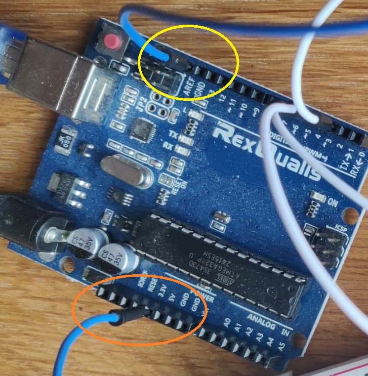
The positive rail is on 5V and the negative rail is on GND.

int latchPin = 4;
int clockPin = 5;
int dataPin = 2;
byte leds = 0;
int currentLED = 0;

void setup()
{
  
    pinMode(latchPin, OUTPUT);
    pinMode(dataPin, OUTPUT);
    pinMode(clockPin, OUTPUT);

    leds = 0;
}

void loop()
{

    leds = 0;

    if (currentLED == 7)
    {
        currentLED = 0;
    }
    else
    {
        currentLED++;
    }

    bitSet(leds, currentLED);

    digitalWrite(latchPin, LOW);
    shiftOut(dataPin, clockPin, LSBFIRST, leds);
    digitalWrite(latchPin, HIGH);

    delay(250);
}


Welcome to the forum

Can someone tell me what I'm doing wrong?

Your first mistake is not telling us what your problem is. What is the sketch meant to do vs what it actually does ?

Please post your sketch, using code tags when you do
Posting your code using code tags prevents parts of it being interpreted as HTML coding and makes it easier to copy for examination

In my experience the easiest way to tidy up the code and add the code tags is as follows
Start by tidying up your code by using Tools/Auto Format in the IDE to make it easier to read. Then use Edit/Copy for Forum and paste what was copied in a new reply. Code tags will have been added to the code to make it easy to read in the forum thus making it easier to provide help.

with such a picture we can't tell the Anode from the cathode of the LEDs. Also the spaghettis seems to go to an untold IC...

So the best answer we can provide is that the proverbial crystal ball is still in the dishwasher...

➜ Please do yourself a favor and read How to get the best out of this forum. Post accordingly, including code with code tags, necessary documentation for your request such as your exact circuit and power supply details, links to components, etc.

1 Like


Closeup shows, I think, positive rail connected to AREF, negative rail connected to 3.3V.

Try positive to 5V, negative to GND.

But I could be wrong.

1 Like

parallax issue in the picture I think

but indeed best if OP clarified...

1 Like

The code works for me. LEDs go on and off in sequence from Q7 to Q0.

It looks like you have GND of the 595 going to two LEDs (red and yellow wires).

Verify all jumper wires at the 595, especially clock and latch pins (H = clock, T = latch).

This is not effecting this program, but you cleared leds twice before using it (by clearing it).

To get a good answer is to post an annotated schematic showing exactly how you have wired it. show all connections, power, ground, power sources etc.

This topic was automatically closed 180 days after the last reply. New replies are no longer allowed.