I'm building my son a really basic battle bot. This is my first arduino project so I keep running head first into problems that are probably obvious to you all. Some examples
You need a pull down resistor across a MOSFET
You need a capacitor across a motor
Old motor controllers consume a ton of voltage
etc.
I was hoping you all could take a look at my schematics to see if there are other problems I can preemptively solve.
I've attached the schematics for both the controller and the bot. The controller has a joystick, a weapon button, and a on / off switch. The bot has 2 drive motors (attached to the DRV8833), weapon motor (attached to the MOSFET), and an on / off switch. The plan was to translate the position of the joystick into PWM duty cycles for the left and right motors. The weapon motor will turn on when the weapon button is clicked and the will turn off if the weapon button is clicked again. The weapons speed will be configurable and will also be controlled by PWM.
Let me know if there are additional detail that I should provide.
rather than capacitors across your motors, it is more typical to have a reverse diode or "snubber" diode which handles reverse voltage spikes when the motor stops. Read this tutorial for how to control you weapons motor using a transistor (and diode)
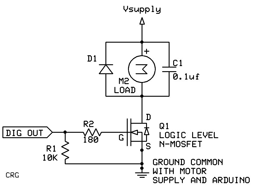
This is maybe a more clear schematic for a brushed DC motor driver. It includes a resistor to limit the current while charging the gate capacitance (R2) and a pulldown resistor (R1) to keep the transistor turned off until the control pin can be set to OUTPUT (the pin will be INPUT ("floating") by default until set to OUTPUT).
Your batteries are drawn the wrong way round, the long line is +ve. An LD33V needs 4.3V minimum so a 3.6V battery won't do it. The MOSFET circuit is upside down. The motor should connect to +ve supply then to MOSFET then to GND and the diode should be across the motor. And your drive motors have both terminals connected to GND...that will never work. That's as far as I got.
Schematics that don't shown what pins you are using are not very useful. One line saying some joystick things connect to some analog things doesn't really help. The schematic should match the code and that obviously needs to use specific pin numbers.
Thanks everyone for your responses. I genuinely appreciate the help. I'm new to this so I hope everyone will bear with me :). My comments inline below.
blh64:
rather than capacitors across your motors, it is more typical to have a reverse diode or "snubber" diode which handles reverse voltage spikes when the motor stops. Read this tutorial for how to control you weapons motor using a transistor (and diode)
I just read that tutorial. Thanks for the link. I (mostly) understand the diode preventing reverse voltage when the motor stops. I added the capacitors to try and even out the voltage when the motors start. Is that not something I have to worry about?
groundFungus:
This is maybe a more clear schematic for a brushed DC motor driver. It includes a resistor to limit the current while charging the gate capacitance (R2) and a pulldown resistor (R1) to keep the transistor turned off until the control pin can be set to OUTPUT (the pin will be INPUT ("floating") by default until set to OUTPUT).
I think that I understand the pulldown resistor but am confused about R2. My understanding of this type of transistor is that current will flow from drain to source when voltage is applied to gate. It looks like R2 is in front of the gate and the capacitor is in front of drain. How does a resistor on the gate effect the drain?
slipstick:
Your batteries are drawn the wrong way round, the long line is +ve. An LD33V needs 4.3V minimum so a 3.6V battery won't do it. The MOSFET circuit is upside down. The motor should connect to +ve supply then to MOSFET then to GND and the diode should be across the motor. And your drive motors have both terminals connected to GND...that will never work. That's as far as I got.
Schematics that don't shown what pins you are using are not very useful. One line saying some joystick things connect to some analog things doesn't really help. The schematic should match the code and that obviously needs to use specific pin numbers.
Have you got any code yet?
Steve
Thanks for letting me know about the LD33V. I'll look for another regulators.
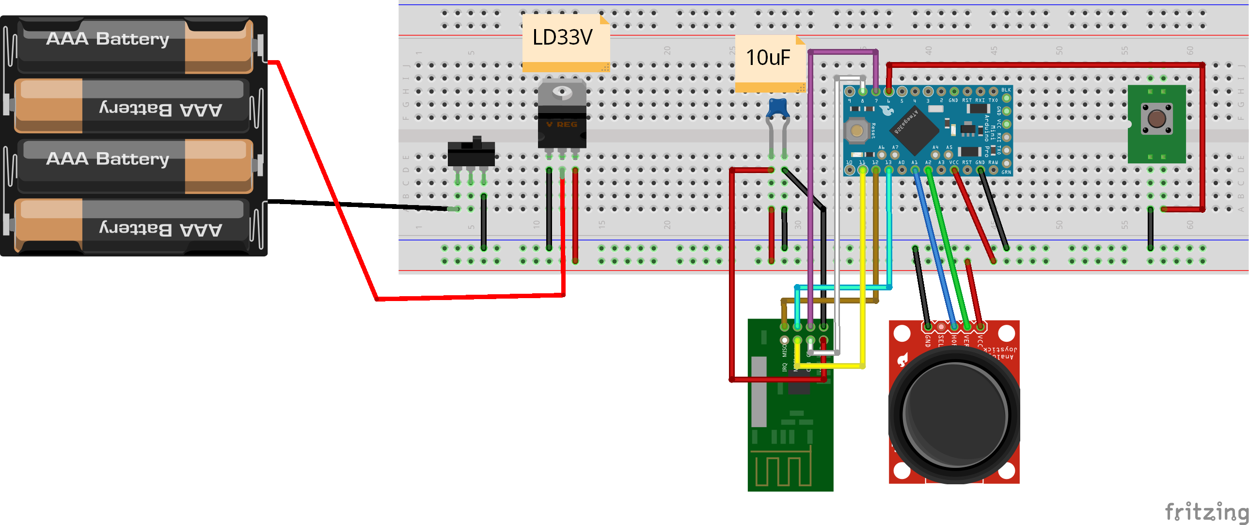
Sorry about the simplified schematics. I thought they would be easier to read. I guess I was wrong :). I've attached more detailed schematics and fritzing diagrams. Let me know if there is more information I should include. Also I wasn't able to find a 3 AAA battery source so I ended up using a 4 AAA battery source.
RE Code. I'm not too worried about the code portion. I have a decent amount of C++ experience and 0 circuit design experience. If I'm going to screw it up its likely on the circuit design :).
It looks like R2 is in front of the gate and the capacitor is in front of drain. How does a resistor on the gate effect the drain?
A property of the MOSFET is that the gate has a certain amount of capacitance. When the Arduino output goes high to turn the MOSFET on the output must charge the gate capacitance. The resistor limits the current out of the output (a cap will look like a short briefly while charging). The capacitance is in the MOSFET, not the one across the motor.
groundFungus:
A property of the MOSFET is that the gate has a certain amount of capacitance. When the Arduino output goes high to turn the MOSFET on the output must charge the gate capacitance. The resistor limits the current out of the output (a cap will look like a short briefly while charging). The capacitance is in the MOSFET, not the one across the motor.
Ah that makes sense. Thanks for the explanation! I added the resistor to my design.
I made a few other changes too
The controller no longer has a LD33V. Instead it has a diode to drop the voltage into a range the rf24 can handle.
The bot now uses 4 AAAs instead of 3. That increases the voltage to what the LD33V expects and the additional voltage will help the motors run faster.
I learned its recommended to have capacitors on both sides of the LD33V so I added 2 10uF capacitors.
I've attached updated schematics including those changes.
Thanks for the help everyone. Any other suggestions would be greatly appreciated :).
johnerrington thanks for your thoughts. My comments inline below.
johnerrington:
I fear your motors will soon flatten AAA batteries - even AA's. You would be best using NiMH.
Rechargeable batteries are a good idea. The motor only uses 1A at stall so I'm not too worried about the batteries. Should I be?
johnerrington:
Another advantage of NiMH is they have a slightly lower voltage - about 1.2 - 1.3 on load; so you dont need a voltage regulator for 5V.
I believe the nRF24L01+ can't run at 5V. If I'm reading it correctly, this datasheet says 1.9 to 3.6. The rechargeable AAAs I have start at 1.3V which, with 3 of them, would be above tolerance. Luckily, I believe I can just put a diode in front of the batteries to drop the voltage to the desired range.
johnerrington:
Anyway, voltage regulators need significant overhead so a 5V regulator will not operate properly from a 6V supply.
If I'm reading this datasheet correctly I believe the LD33V can run at 4.3V. My new plan of running 4 AAAs for the bot should get above 4.3V
johnerrington:
My site may have some info you will find useful as it focusses mainly on the electronics side of arduino projects
GooperMC:
The motor only uses 1A at stall so I'm not too worried about the batteries. Should I be?
I believe the nRF24L01+ can't run at 5V. If I'm reading it correctly, [
Load surge current can do some crazy things, so best to have plenty of battery capacity.
Would be best to use the available adaptor which runs on 5V and supplies the NRF24 with correct voltage as it will take care of power requirements there also.
as a ROUFGH guide the max current you should normally draw from a cell is its 2 hour rating - so for an 800mAh AAA 400mA; for a 2400mAh AA 1.2A.
I did a bit of research and it looks like NiMh batteries do better under higher loads than Alkaline. My new plan is 4 NiMh AA's for the bot. It looks like NiMh AAs can produce 2.5A fairly easily and can produce up to 5A but run out of juice quickly link. My motors produce 1A at stall but only 350mA during normal use. Seems like 4 AAs should be able to handle this load for a while. Does my logic make sense to you all?
bluejets:
Load surge current can do some crazy things, so best to have plenty of battery capacity.
Would be best to use the available adaptor which runs on 5V and supplies the NRF24 with correct voltage as it will take care of power requirements there also.
Yep good point. My new plan is to use the onboard regulator and 4 AAs. Do you think that will work?
I did a bit of research and it looks like NiMh batteries do better under higher loads than Alkaline.
yes so did I - more info on my site, and you'll see the graph.