CANBED V1 decided it wouldn’t operate on Automotive 12V and died?

Long time lurker, first time poster

Basic explanation about what I am trying to do, receive CANBUS information from my aftermarket ECU (Haltech 750) in my drift car and display certain data on a 2.4” screen

Will copy/paste what I posted on a niche Facebook Group below, any advice/criticism is welcome!

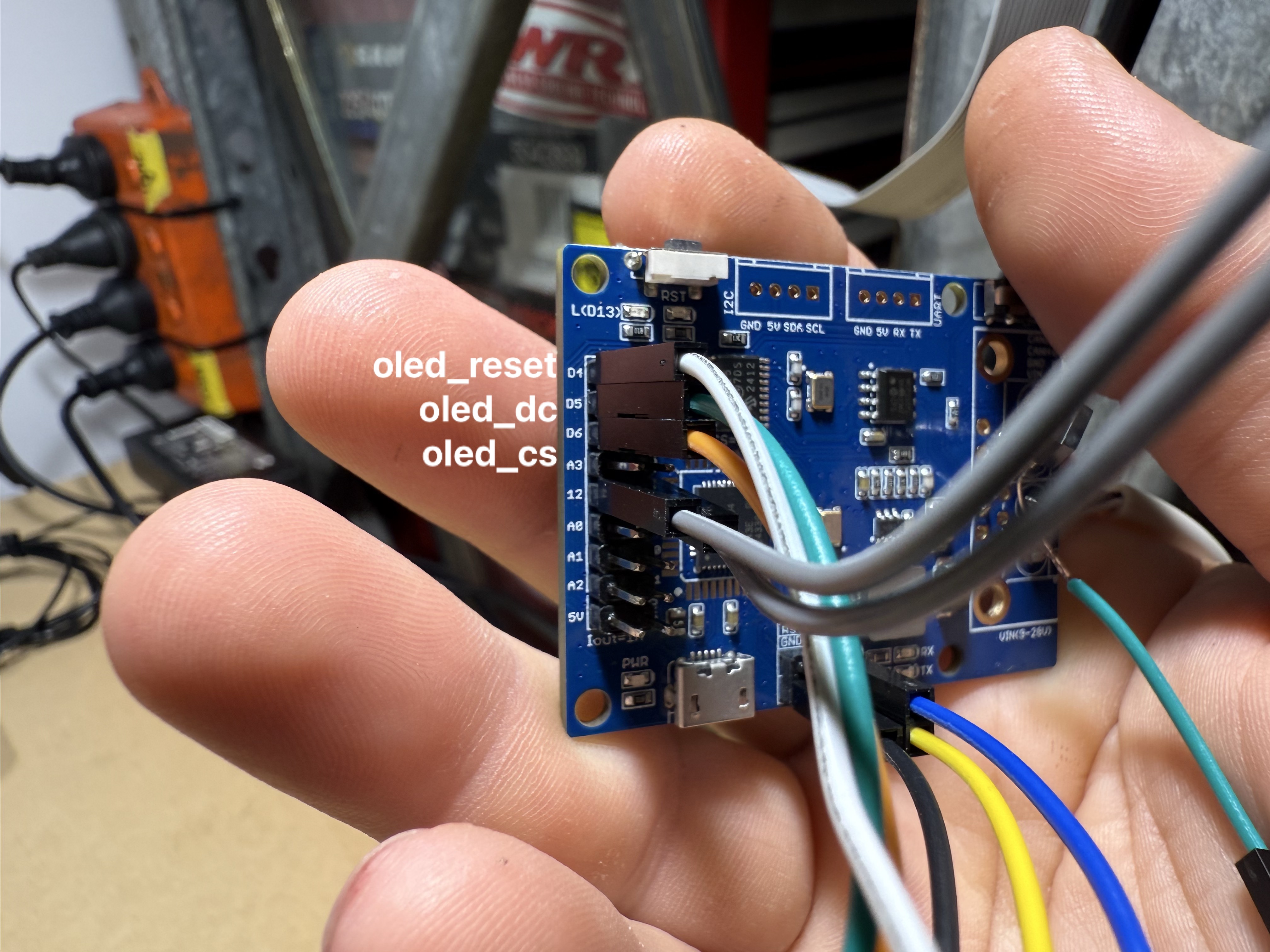
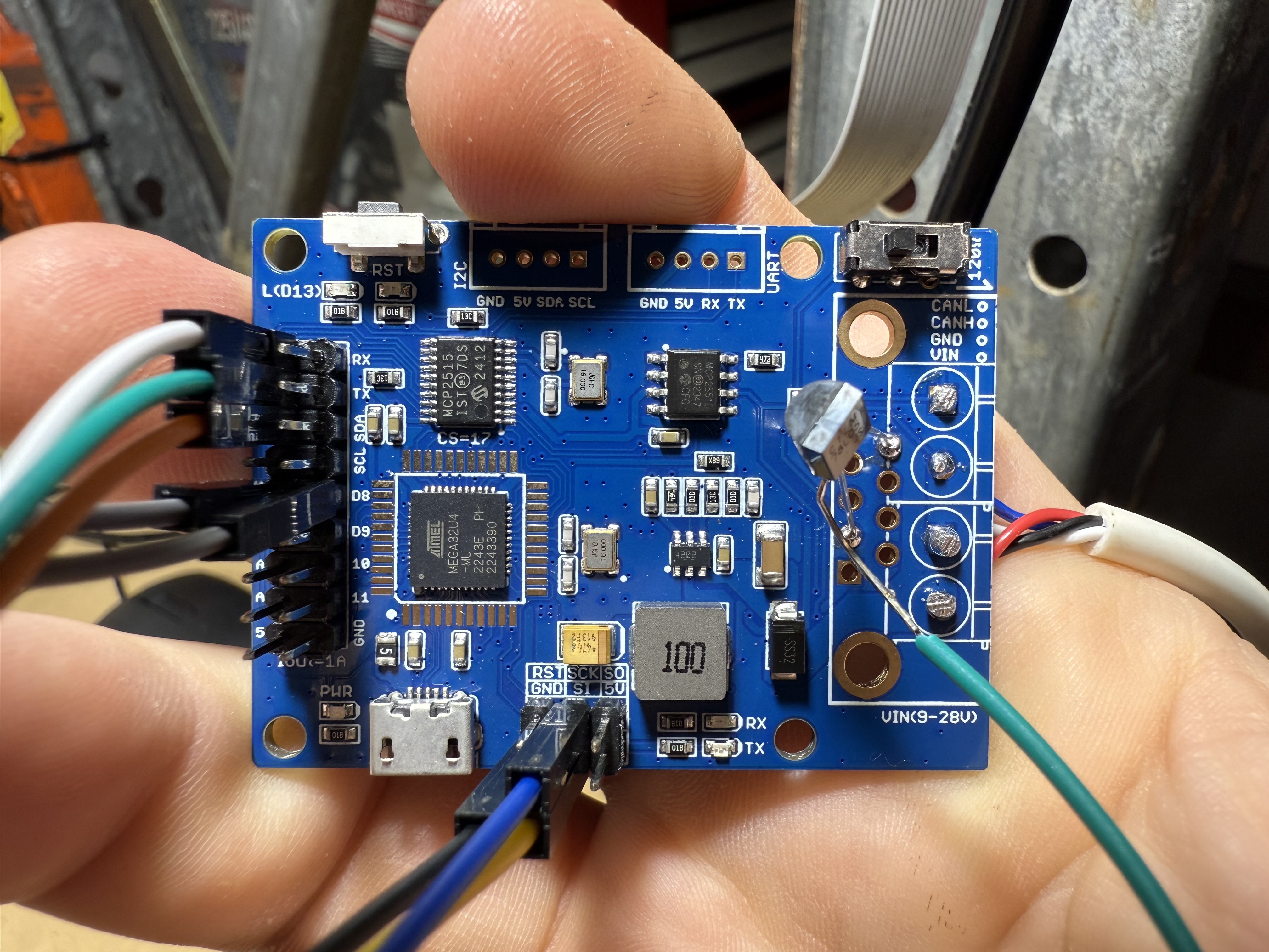
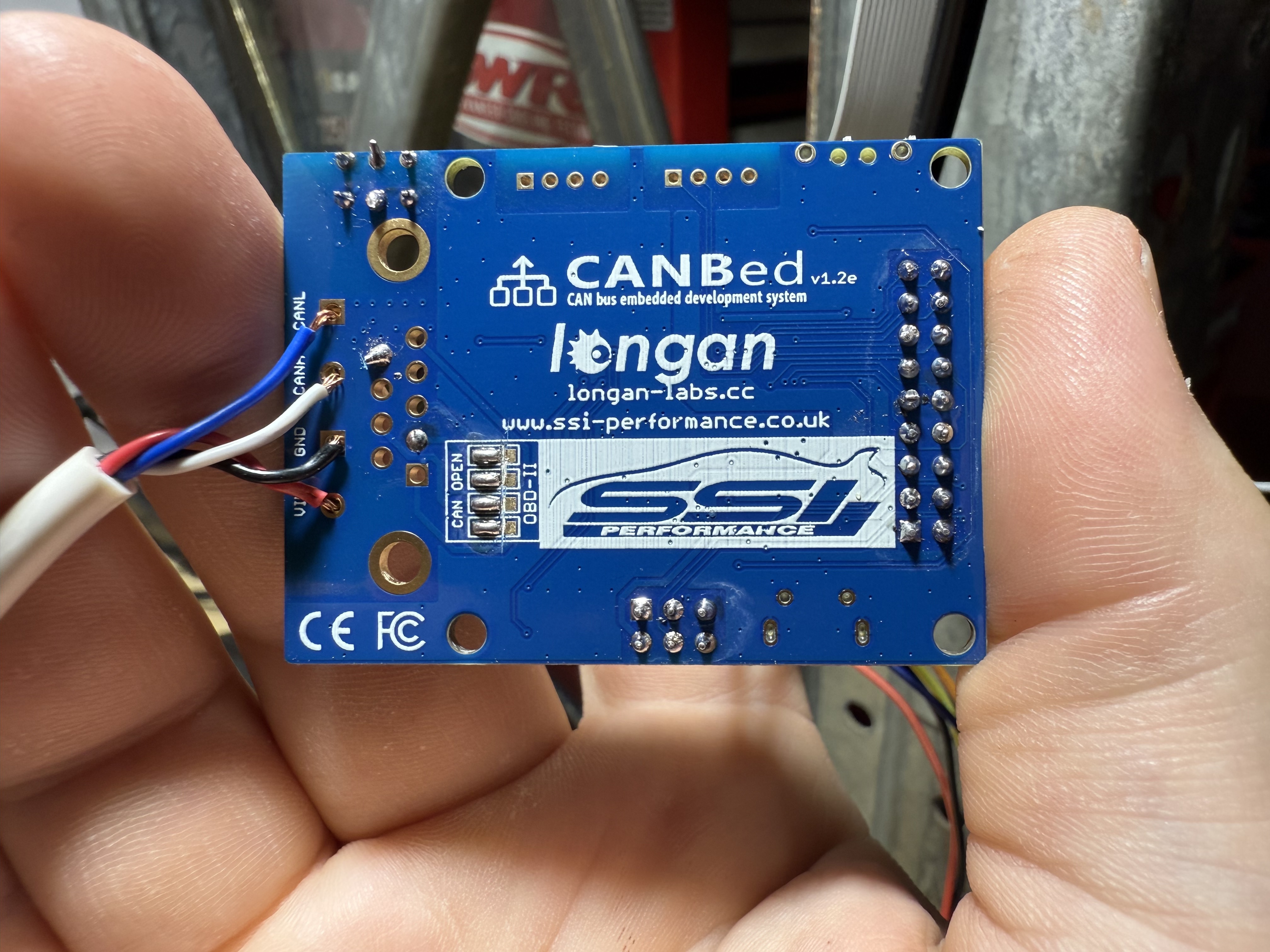
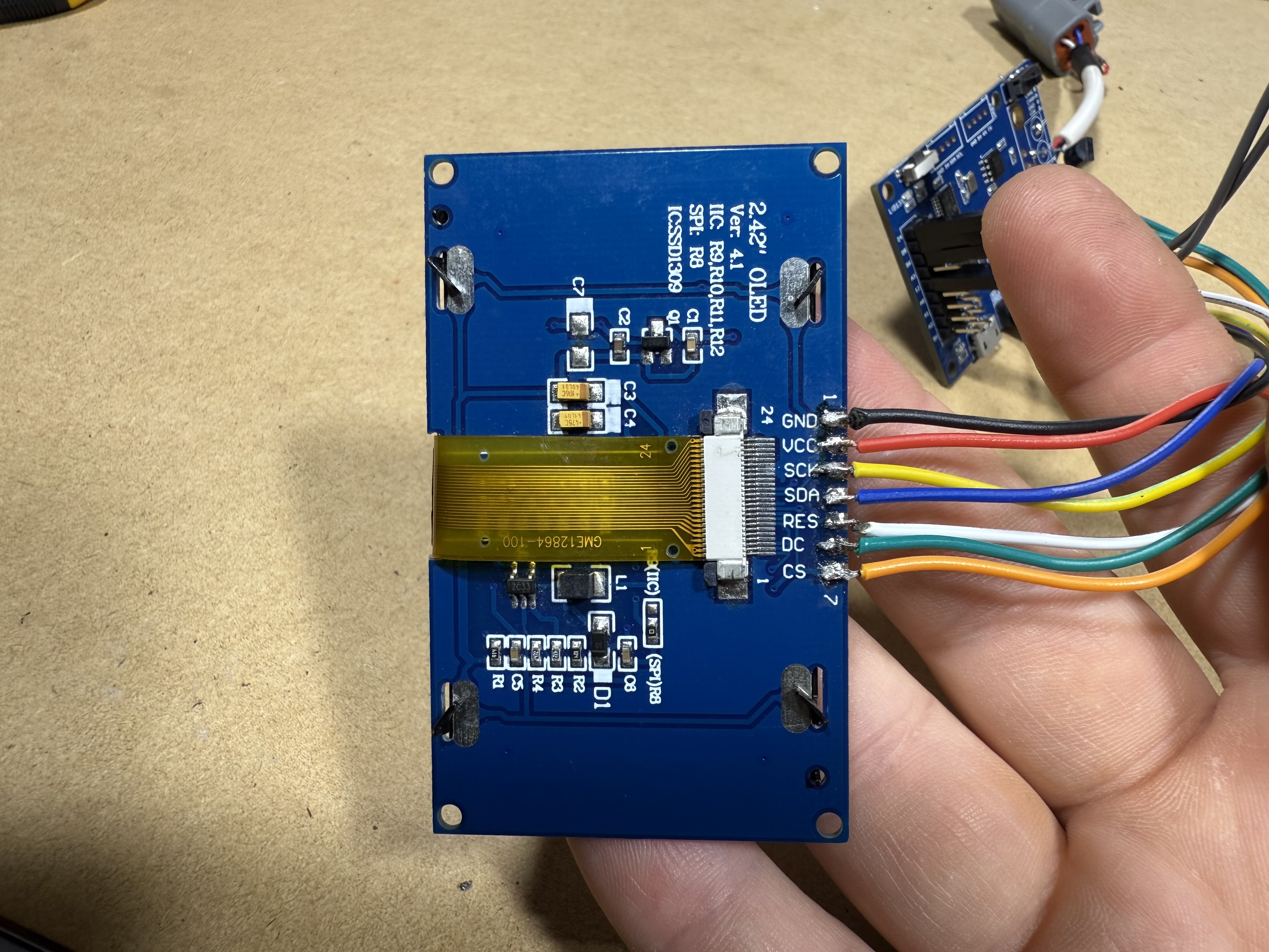
‘Overview: Haltech Elite 750, WB1 controller, CAN Cable plugged into WB1 controller, SSD1306 Screen running with Hardware SPI, CANBED V1 board

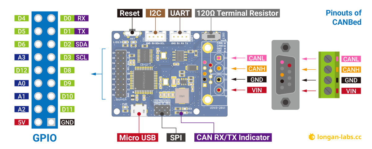
Ditched the second hand Hobbytronics board I was using and ended up getting a CANBED V1 board and used a random 2.4” screen I had laying around to get it working

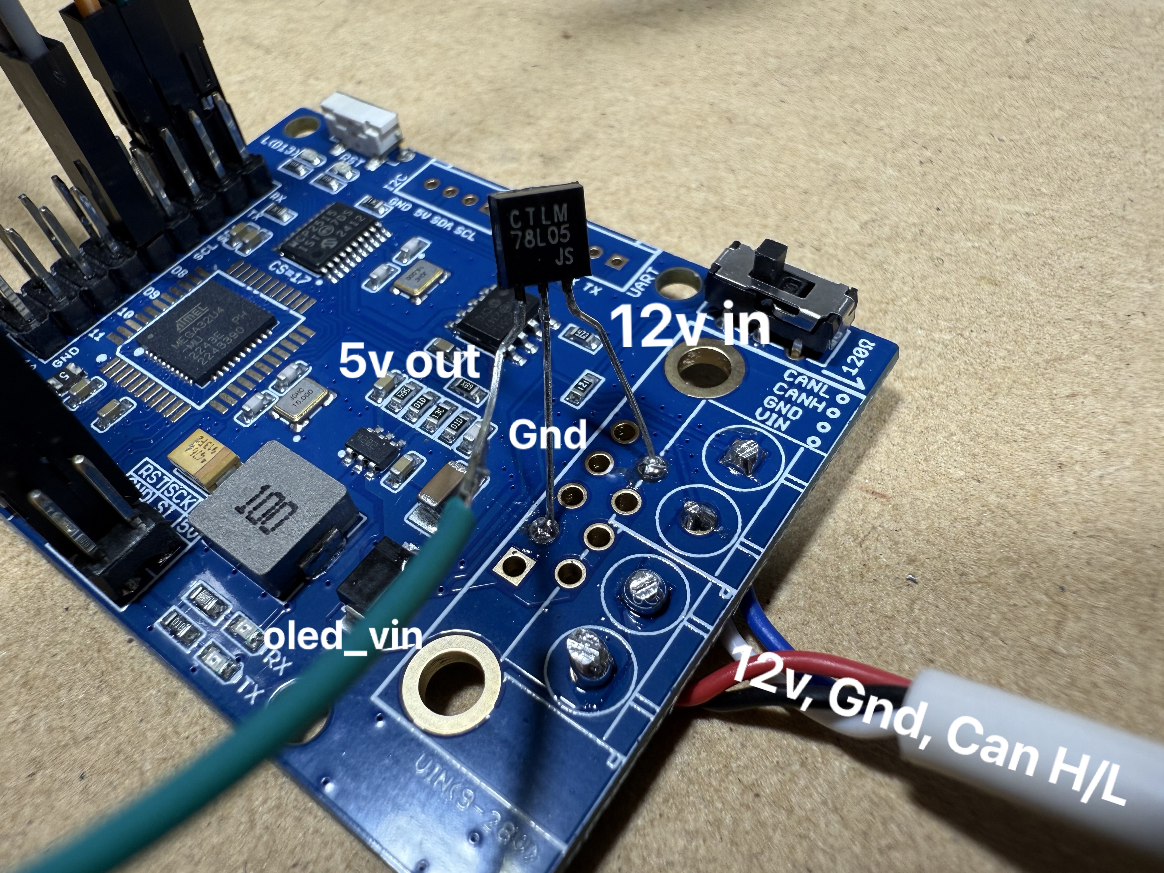
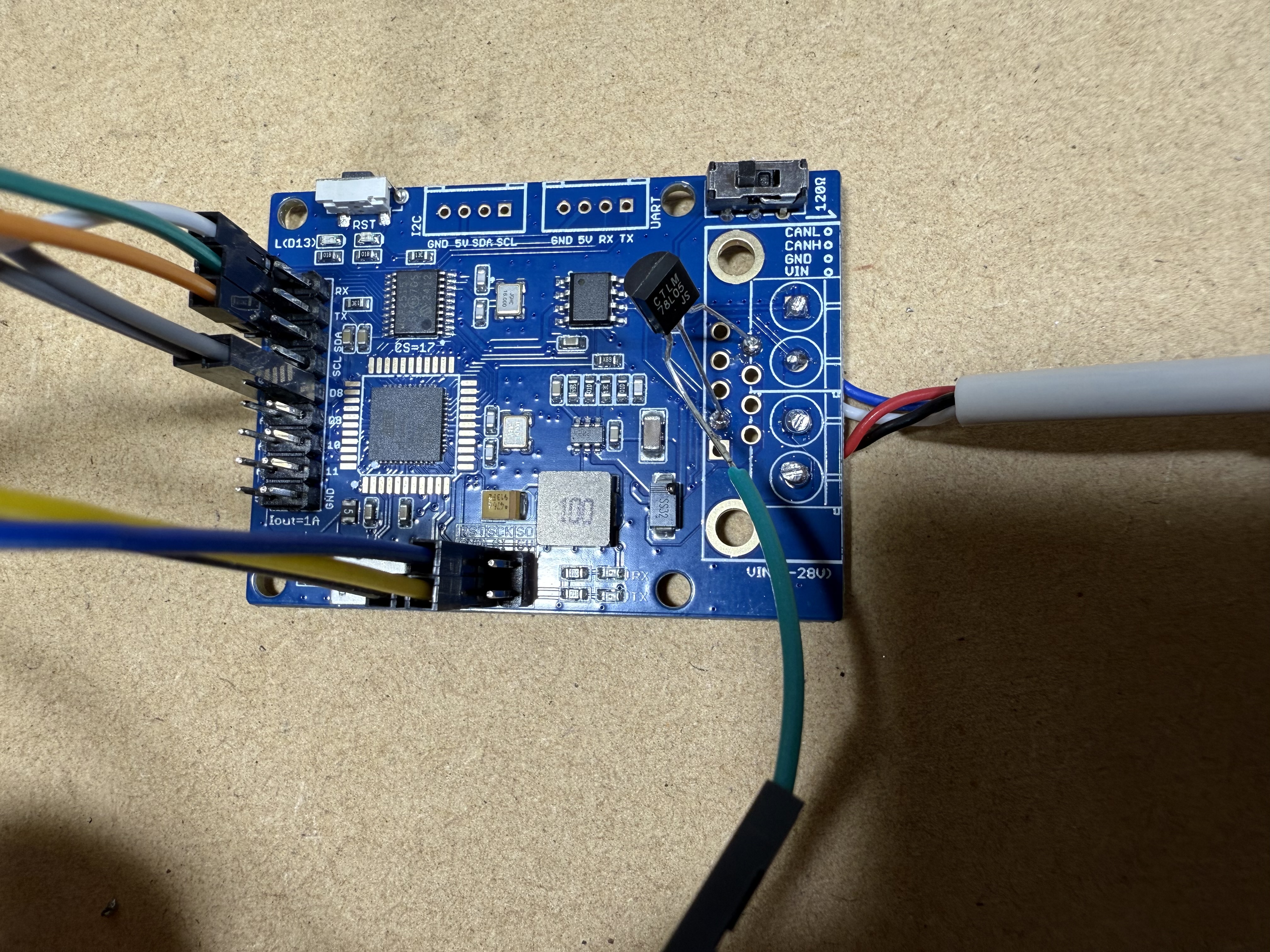
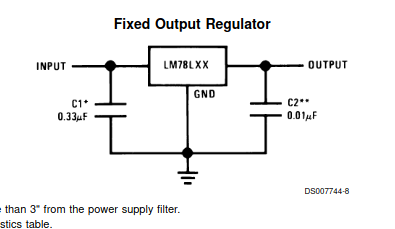
Used a bit of the ELITE GAUGE code as a base to adapt for my setup/use, also adopted an L78L05 to give the screen 5v power as the board wasn’t happy supplying the screen 5v from its ICSP header while also receiving CAN stream (no idea why)

Everything was running swell when I just had ignition on, but it all went to shit when I started the car and the CAN positive went from 12v to 13.9v, Voltage regulator died (weird as it should be able to handle up to 35v input voltage) and killed the screen, presumably killed the board and possibly killed my Wideband Controller as it was sending 7v from the Voltage regulator ground down the CAN ground

Can someone explain what/where I went wrong

Arduino/Coding is the most difficult thing I’ve ever taught myself and I thought I could see light at the end of the tunnel until I let the smoke out of the voltage regulator’

Thanks for reading

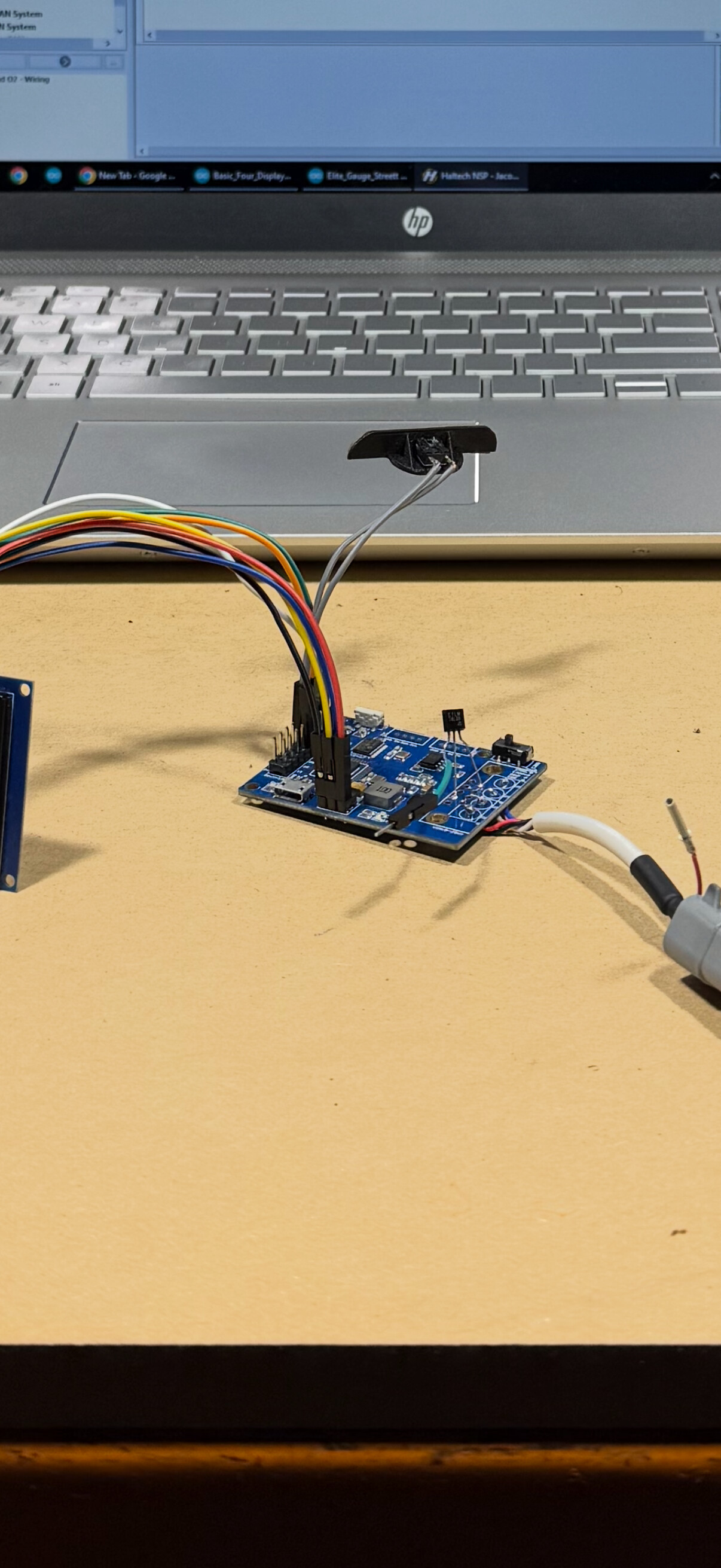
Attached is a photo of my basic setup

‘Rough idea of my setup. When it was all working, I had the red wire from the screen plugged into the green wire coming from the Vo of the Voltage regulator’

The automotive environment is one of the harshest environments for electronics there is.

Without proper circuit protection your arduino etc. did not stand a chance.

Here is a pdf that describes the issues and one possible way to address them.
https://www.google.com/url?sa=t&source=web&rct=j&opi=89978449&url=https://www.st.com/resource/en/application_note/an2689-protection-of-automotive-electronics-from-electrical-hazards-guidelines-for-design-and-component-selection-stmicroelectronics.pdf&ved=2ahUKEwj-0sXrnf-KAxXP4MkDHWEIPFYQFnoECB0QAQ&usg=AOvVaw2kL-p13bMPYWqoklQmqbZd

Whatever sent you the 13.9 V reading, is probably wrong. To measure a voltage with a multimeter you might end up with 13.9 V. Connect a oscilloscope and now you see these spikes appearing, that the multimeter couldn't detect because it's too slow. And as @Hutkikz say...

You can have really nasty spikes in a cars electrical system. This is just all theory though, that overvoltage killed your Arduino.

The picture is ... well not very revealing. It's like watching a photo of someone and tell what kind of person they are. We need a diagram / schematics. The more detailed the better help you'll get.

Without causing any disrespect, I’m not prepared to learn all of the jargon in that PDF to make sense of it

My setup worked well (under the conditions I was under the assumption of as being within its limits) software/hardware/coding wise, my question was in relation to why the board designed for automotive use and a Voltage regulator rated to 35v input voltage didn’t take on board a standard passenger vehicle charging rate of ~13.9v

A multimeter is all I have on hand, as my knowledge base is purely automotive 12v, I have never had a need to use an oscilloscope

I was under the assumption that as I was using a Wideband controller that is powered via a DTM4 connector with CAN High and Low from the ECU as a CAN hub, that any voltage that was sent through it would be consistent

I will get better photos/schematic tomorrow

Good.

Priority: 1) Schematics reveal the build and components used, 2) photos if something visibly failed, or something was connected wrong.

Hopefully quality/resolution of these photos is fine

Mind the soldering job, was using this board as a proof of concept board

Not pictured is the rest of the setup in my car, uneventful in regards to this setup, links in with a half metre-ish cable with a DTM4 connector

Didn’t realise new users could only upload three at a time, here’s the final three

They are, but still nothing compares to a proper schematics.

That 3 legged transistor-look-a-like is the regulator I assume. Does it power everything 5 V or is there some other regulator?

Btw do you got a link to the datasheet?

I can’t find a true schematic unfortunately, closest thing is this

Datasheet for Voltage regulator is here

The three legged regulator only powers the screen, there is an onboard regulator somewhere that brings the 12v from CAN down to 5v for the board to operate

So that's the regulator that malfunctioned. I guess it shorted and 12 V or more went berserk. There's a very likely reason to this: I don't see any caps accompanying the regulator. This is from the datasheet.

Running voltage regulators without capacitors can make them oscillate, and that will stress them. I would in addition to C1 add an electrolyte rated 63 V before C1, maybe a Zener too, as an increased protection against voltage spikes.

That's is the worst time for electronics.

Having a quick google now, what uF should I be aiming for, and how would I arrange the setup if I was to incorporate a zener diode as well as a capacitor for the screens voltage regulator?

The other board that had a L78L05 wired in the same way didn’t have any of this additional hardware so I’m unsure

Without knowing your skill level or the tools you have available, it seems the design may have been created without sufficient knowledge of automotive electronics and the associated pitfalls. The following links will not be helpful unless you take the time to understand the concepts they cover. I recommend spending some time studying them thoroughly. You probably got hit with a load dump transient.

Valuable Resources for Automotive Electronics:

  1. STMicroelectronics Application Note AN2689:
    This application note provides guidelines on protecting automotive electronics from electrical hazards, focusing on design and component selection. Reading this will greatly enhance your understanding of automotive circuit protection.
    Read AN2689
  2. Analog Devices: Automotive Electronics Design:
    This article distills key insights into designing automotive electronics, offering practical advice for engineers.
    Read the article
  3. Diodes Incorporated: Transient Voltage Suppression in Automotive:
    Learn about techniques to protect automotive circuits from transient voltage, which is critical for ensuring reliable operation in harsh conditions.
    Read the article
  4. AEC-100 Standards Webinar:
    This webinar from Monolithic Power Systems provides a detailed overview of AEC standards, essential for understanding automotive electronics requirements.
    Watch the webinar
  5. Understanding Automotive Electronics, An Engineering Perspective by William B. Ribbens:
    This comprehensive book offers an in-depth look into automotive electronics from an engineering perspective, making it an invaluable resource.
    Access the book
  6. Application Note https://www.ti.com/lit/an/slvafc1/slvafc1.pdf?ts=1652591872294

These resources should provide a strong foundation for anyone involved in automotive electronics design. If you need further help or more resources, feel free to ask!

You need to use automotive rated components especially when connecting to the vehicle's electrical system.

Different circumstances. One of the things to learn if you're serious about EE is to check for manufacturers recommendations. They are there for a reason.

This is an suggestion, nothing else. But it will give you much better chance of keep the circuit healthy :slight_smile:

I skipped the Zener to keep it simple.

1 Like

To be added: The Farad value for C1 are not set in stone.

C1 is an electrolyte
C2 C3 are ceramics

Appreciate the help

This project started off as a ‘buy a board, chuck a screen on and load the Open Source Code’ but it has snowballed a bit beyond that.

I never thought to check the data sheet for the regulator, seems like a daft oversight in hindsight .

What does the manufacturers data sheet say, not all 7805s will live with 35V on the input. This one will take only 30V. https://siliconsupplies.com/media/literature/ss/78L05%20REV%202.pdf I have seen some as low as 21V.

There's a saying in Swedish 'friskt kopplat hälften brunnet'. Roughly translated 'opportunisticly connected, half burned'.

Most of us have done it, but in your case perhaps more costly since the electronics is more niche.

This is the datasheet for the regulator, my specific reg is the first listed

Great, what protects the regulator from getting voltages over 35V. Read the first page of this app note and look at the lower right hand corner. https://www.ti.com/lit/ab/snoaaa1/snoaaa1.pdf? There are also negative transients that you need to protect from. Spend the time and read the links I posted previously.