I FIGURED THIS OUT FOR PEOPLE FACING SIMILAR ISSUES SEE BELOW
Thanks for all the help y'all, unfortunately no one accounted for my general incompetence when it comes to understanding basic logic. I had my SDO from the MAX31865 connected to my "SDO" pin on the Arduino. My monkey brain assumed this was a matching game and there was no communication at all. Data Out needs to be connected to Data In. Everything is working fine.
Hello all, I am very new to Arduino and I am trying to read temperature off a PT100. I have bought to sensors and two MAX31865 boards from two different suppliers and I am getting similar problems. I am guessing its something to do with my heavy handed attempt at soldering the MAX31865 with my 5$ iron, or a mistake in my code. My temperature readings read at -252 repeatedly seen below.

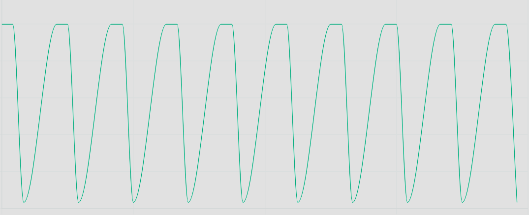
When I looked at the serial plotter it seems to fluctuate?
I have confirmed both PT100's work correctly, and my max 31865 RRef is marked 431, which is correct for the PT100. I confirmed this as well with my multimeter.
Im using an Elegoo UNO R3, and confirmed its SPI ports

I have tried configuring my code for both hardware and software SPI, but still am a bit confused on the difference. Here is the code I used for "hardware"
#include <SPI.h>
#include <Adafruit_MAX31865.h>

// Use hardware SPI, just pass in the CS pin
Adafruit_MAX31865 thermo = Adafruit_MAX31865(10); // CS pin connected to pin 10

// The value of the Rref resistor. Use 430.0 for PT100 and 4300.0 for PT1000
#define RREF      430.0
// The 'nominal' 0-degrees-C resistance of the sensor
// 100.0 for PT100, 1000.0 for PT1000
#define RNOMINAL  100.0

void setup() {
  Serial.begin(115200);
  Serial.println("Adafruit MAX31865 PT100 Sensor Test!");

  thermo.begin(MAX31865_3WIRE);  // Set to 2WIRE or 4WIRE as necessary
}

void loop() {
  uint16_t rtd = thermo.readRTD();

  Serial.print("RTD value: "); Serial.println(rtd);
  float ratio = rtd;
  ratio /= 32768;
  Serial.print("Ratio = "); Serial.println(ratio, 8);
  Serial.print("Resistance = "); Serial.println(RREF * ratio, 8);
  Serial.print("Temperature = "); Serial.println(thermo.temperature(RNOMINAL, RREF));

  // Check and print any faults
  uint8_t fault = thermo.readFault();
  if (fault) {
    // Handle faults here
  }

  Serial.println();
  delay(1000);
}
On my breadboard, I have the following connections.
ELEGOO | BREADBOARD | BREADBOARD | MAX31865
3.3V → PositiveRail → c8, c6, → Vin, 3V3
GND → GroundRail → c7 → GND
Pin13(SCK) → N/A → c5→CLK
Pin12(MISO) → N/A →c4→ SDO
Pin11(MOSI) →N/A→c3→SDI
Pin10(SS)→N/A→c2→CS
The final pin on the MAX31865 (RDY) is not used.
When attempting to connect my ELEGOO's 5Vout to the VIN of the MAX31865 when GND is connected, or vice-versa, my ELGOO shuts off. This does not happen when I connect the 3.3V to the positive rail of the board, then the 3v3 from the MAX to the positive rail, and 3.3V output to the positive rail. It dose turn off no matter which GND port I use when trying to use 5V.
I have checked all cut traces and test points on the board. It is all correct. This has been driving me and my wallet crazy. If anyone can help me figure out what I'm doing wrong I would greatly appreciate it. Thanks in advance! And let me know if you need any other information from me.