Can't get code to work/upload Atmega4808

Hi! I am a total beginner in using Arduino, so I am very confused. Sorry if I am doing something obviously wrong here that I shouldn't have missed.

I am trying to make a temperature logger that measures surface temperature every 15 minutes using the Mini Ultra board with atmega4808 (https://www.rocketscream.com/blog/product/mini-ultra/), MLX90614 sensor, Adafruit MicroSD SPI or SDIO Card Breakout Board, and using 2 x AA batteries as a power source. I am using the UPDI-USB-Serial Adapter V2 to connect the board to IDE (https://www.rocketscream.com/blog/product/updi-usb-serial-adapter-v2/)

Using my code I have made it work correctly on several different boards, but not this one. But I do not get an error message, the IDE program acts as if it works, but then nothing happens..
This is the code:

#include <SPI.h>
#include <SD.h>
#include <Adafruit_MLX90614.h>

Adafruit_MLX90614 mlx = Adafruit_MLX90614();

const int chipSelect = 0;
// change to the digital pin used on board

void setup() {
  // Open serial communications and wait for port to open:
  Serial.begin(9600);
  while (!Serial) {
    ; // wait for serial port to connect. Needed for native USB port only
  }

  Serial.print("Initializing SD card...");

  // see if the card is present and can be initialized:
  if (!SD.begin(chipSelect)) {
    Serial.println("Card failed, or not present");
    // don't do anything more:
    while (1);
  }
  Serial.println("card initialized.");

  if (!mlx.begin()) {
    Serial.println("Error connecting to MLX sensor. Check wiring.");
    while (1);
  };

  File dataFile = SD.open("datalog.csv", FILE_WRITE);
  String header = "";
  if (dataFile)
  {
    header += String("Time");
    header += ",";
    header += String("Ambient 1");
    header += ",";
    header += String("Object 1");
    header += ",";
    header += String("Ambient 2");
    header += ",";
    header += String("Object 2");
    header += ",";
    header += String("Ambient 3");
    header += ",";
    header += String("Object 3");
    header += ",";
    dataFile.println(header);
    dataFile.close();
  }
}

void loop() {
  // make a string for assembling the data to log:
  String dataString = "";
  Serial.print("Ambient = "); Serial.print(mlx.readAmbientTempC());
  Serial.print("*C\tObject = "); Serial.print(mlx.readObjectTempC()); Serial.println("*C");
  
  dataString += String(millis());
  dataString += (",");
  
  dataString += String(mlx.readAmbientTempC());
  dataString += String(",");
  dataString += String(mlx.readObjectTempC());
  dataString += String(",");

  delay(1000);
  Serial.print("Ambient = "); Serial.print(mlx.readAmbientTempC());
  Serial.print("*C\tObject = "); Serial.print(mlx.readObjectTempC()); Serial.println("*C");
  dataString += String(mlx.readAmbientTempC());
  dataString += String(",");
  dataString += String(mlx.readObjectTempC());
 
  // open the file. note that only one file can be open at a time,
  // so you have to close this one before opening another.
  File dataFile = SD.open("datalog.csv", FILE_WRITE);

  // if the file is available, write to it:
  if (dataFile) {
    dataFile.println(dataString);
    dataFile.close();
    // print to the serial port too:
    Serial.println(dataString);
  }
  // if the file isn't open, pop up an error:
  else {
    Serial.println("error opening datalog.csv");
  }
  
  Serial.println();
  delay(30000);

}

And here is a very simple illustration made in pain of how I have connected everything, followed by the pinout of the board:


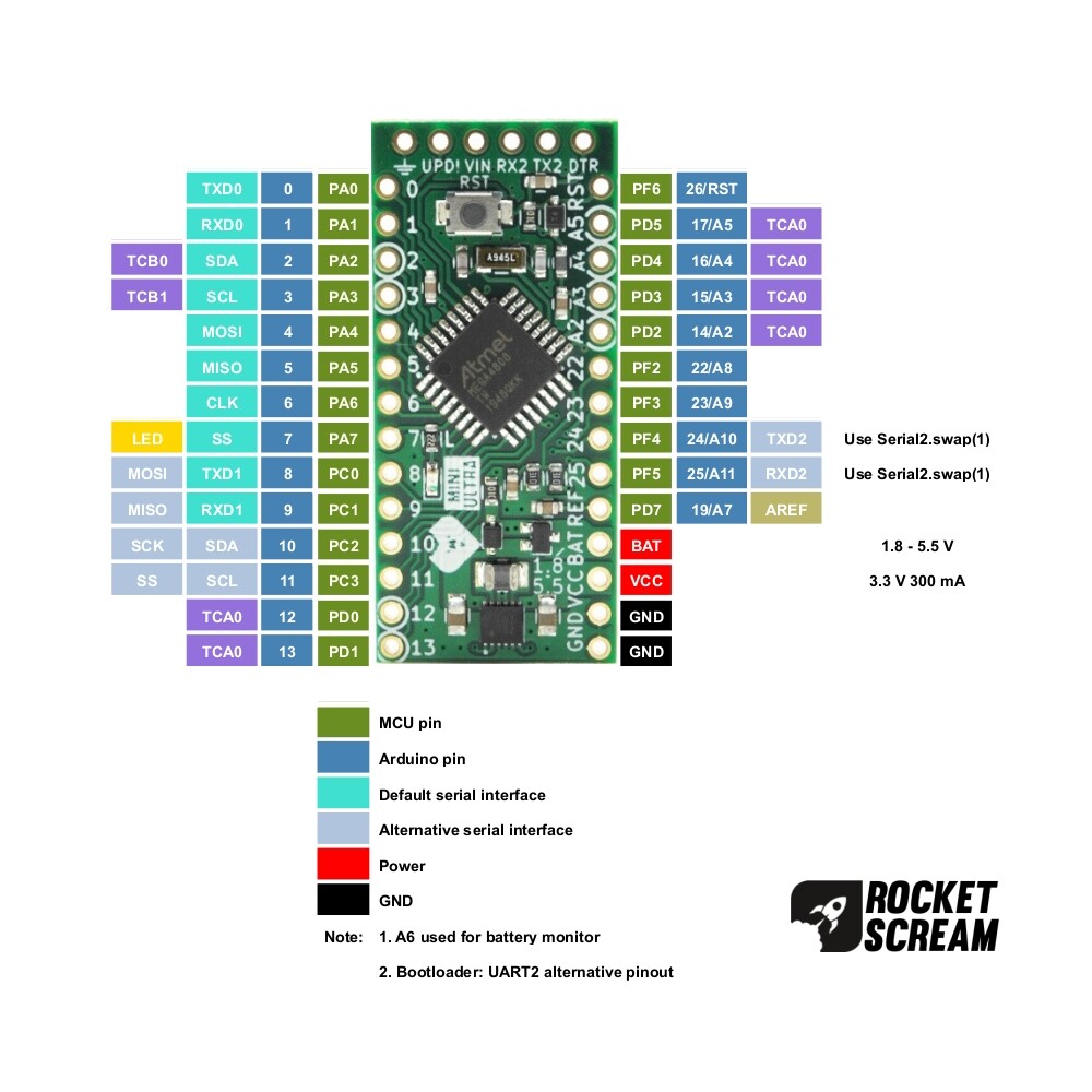
I can also note that the sensor example code nor the SDcard info code (found under examples in IDE) does not work, but the "Blink" example does work. My code above, and all the examples works when I connect to Nano Every (4809), Arduino MKR WIFI 1010, or an Arduino MKR Zero, but I need it to work with Mini Ultra for my project.

I am using MegacoreX and programmer Jtag2updi.

Any help or feedback is appreciated!
Thanks

Maybe i'm interpreting your diagrams incorrectly, but it looks like you are using pin 4 for MOSI, pin 5 for MISO, pin 10 for SCK and pin 0 for SS.

The RocketScream picture shows MOSI, MISO, SCK and SS on pins 4, 5, 6 & 7. According to the MegaCoreX docs, pins 4, 5, 6 & 7 are the default pins for SPI.

I would try connecting the SD card CLK to pin 6, rather than pin 10.

I guess you can use whatever pin you like for your SS.

1 Like

Yes, you interpreted my digrams correct :slight_smile: I put it as pin 10 (SCK) because I was following some wiring examples for the SD card, and the other boards I have tried haven't had a CLK pin like this one! I will try switching it from pin 10 to pin 6 as you suggested, but shouldn't the MLX example code still work? Also does a CLK pin and SCK pin have the same function?

Thanks for the input! I will try it out and update when I get home (1-2 hours), as I am on the train now! :slight_smile:

If you are referring to pin 6 in the RocketScream image, then I believe that CLK = SCK in this case. I think that's likely a typo in the RocketScream docs.

1 Like

Now it works!!
After using 4, 5, 6, and 7 for the SD board, and changing the pin number in the code to 7 I got the board to work! In IDE nothing shows up on "monitor" but after disconnecting it and letting it work for 5 minuets it now creates an cvs file with the temperature measurements in it.

Thank you very much!

Now that the sensor and SD reader works, I was just wondering why the Serial Monitor in Arduino IDE does not work with the Atmega4808?
Is there a way to "turn it on"?

Even if there isn't, the most important thing was to make it actually log the temperature! :slight_smile:

Which IDE version...??
Plenty of online instruction.

I was just wondering why the Serial Monitor in Arduino IDE does not work with the Atmega4808?

This board looks like it has a USB interface based on the WCH’s CH342F.
Do you have a driver for this interface chip on your PC?

I thought I had, but upon further inspection maybe I chose the wrong driver?

On the UPDI adapter page they link to this webpage:

I think I downloaded and installed the "CH343SER.EXE", which I see now does not say CH342F.. Although nothing else on that link does either, so then I'm not quite sure what to download and use. :thinking: :slight_smile:

There's several steps to getting this working.

Firstly, does your PC detect the serial-USB adapter board? Does it give you a new COM port when you plug it in? If it doesn't, then you need to install the driver for it as @cattledog suggested.

Secondly, are you connecting to TX2 & RX2 at the top of the board or TX0 & RX0 on pins 0 & 1.

If it's TX0 & RX0, then Serial is the port to use, and your code should work. If it's TX2 & RX2, then Serial2 is the port to use.

This assumes that you don't need to do any pin swaps.

1 Like

Thanks for all the feedback!

Yes, when I plug it in port 12 and 13 shows up as choices in IDE. Not sure why I get 2 options, but one of them works.

I am connecting TX on the UPDI device to RX2 on top of the board, and RX on the UPDI device to TX2 on top of the board as such:


So then I need to use Serial2? I didn't realize there was more than one Serial, but I will go over the code and change Serial to Serial2 now.
Will update here when I have tested it!

So I still can't get it to show up in Serial Monitor. I changed my code to:

#include <SPI.h>
#include <SD.h>
#include <Adafruit_MLX90614.h>

Adafruit_MLX90614 mlx = Adafruit_MLX90614();

const int chipSelect = 7;
// change to the digital pin used on board

void setup() {
  // Open serial communications and wait for port to open:
  Serial.begin(9600);
  Serial2.begin(9600);
  while (!Serial2) {
    ;  // wait for serial port to connect. Needed for native USB port only
  }

  Serial2.print("Initializing SD card...");

  // see if the card is present and can be initialized:
  if (!SD.begin(chipSelect)) {
    Serial2.println("Card failed, or not present");
    // don't do anything more:
    while (1)
      ;
  }
  Serial2.println("card initialized.");

  if (!mlx.begin()) {
    Serial2.println("Error connecting to MLX sensor. Check wiring.");
    while (1)
      ;
  };

  File dataFile = SD.open("datalog.csv", FILE_WRITE);
  String header = "";
  if (dataFile) {
    header += String("Time");
    header += ",";
    header += String("Ambient 1");
    header += ",";
    header += String("Object 1");
    header += ",";
    header += String("Ambient 2");
    header += ",";
    header += String("Object 2");
    header += ",";
    header += String("Ambient 3");
    header += ",";
    header += String("Object 3");
    header += ",";
    dataFile.println(header);
    dataFile.close();
  }
}

void loop() {
  // make a string for assembling the data to log:
  String dataString = "";
  Serial2.print("Ambient = ");
  Serial2.print(mlx.readAmbientTempC());
  Serial2.print("*C\tObject = ");
  Serial2.print(mlx.readObjectTempC());
  Serial2.println("*C");

  dataString += String(millis());
  dataString += (",");

  dataString += String(mlx.readAmbientTempC());
  dataString += String(",");
  dataString += String(mlx.readObjectTempC());
  dataString += String(",");

  delay(1000);
  Serial2.print("Ambient = ");
  Serial2.print(mlx.readAmbientTempC());
  Serial2.print("*C\tObject = ");
  Serial2.print(mlx.readObjectTempC());
  Serial2.println("*C");
  dataString += String(mlx.readAmbientTempC());
  dataString += String(",");
  dataString += String(mlx.readObjectTempC());

  // open the file. note that only one file can be open at a time,
  // so you have to close this one before opening another.
  File dataFile = SD.open("datalog.csv", FILE_WRITE);

  // if the file is available, write to it:
  if (dataFile) {
    dataFile.println(dataString);
    dataFile.close();
    // print to the serial port too:
    Serial2.println(dataString);
  }
  // if the file isn't open, pop up an error:
  else {
    Serial2.println("error opening datalog.csv");
  }

  Serial2.println();
  delay(30000);
}

Basically just putting a 2 after every Serial.
Is this the wrong way to choose a serial port? I can't find any options under "Tools" in IDE.

(The code does still work, and it measures and logs the temperature).

That would be what I would have done. The assumption being that the TX2 and RX2 labels on your board do indeed refer to Serial2.

What does the documentation for your board say?

However, I would have thought that the designers would have set up the board so that Serial was routed to the TX2 and RX2 pins as that is the most obvious place a user would be expected to connect their USB-Serial adapter.

I will have a look and see if there are any details on the RocketScream website and see how they compare to the MegaCoreX documentation.

You could adopt the scattergun approach. The 4808 has 3 serial ports. Hopefully they are defined as Serial, Serial1 and Serial2.
You could try this very basic bit of code:

void setup() {
  Serial.begin(9600);
  Serial.begin1(9600);
  Serial.begin2(9600);
}
void loop() {
  Serial.println("Serial");
  Serial1.println("Serial1");
  Serial2.println("Serial2");
  delay(1000);
}

And see what appears on your IDE serial monitor. Remember to set the IDE serial monitor baud rate to 9600 baud.

EDIT: Silly typo on my part! begin1 & begin2 - really, what was I thinking....

I tried the code you suggested, but got the error:

C:\Users\Sara Linn\AppData\Local\Temp\.arduinoIDE-unsaved202356-4308-1ml080c.ed13\sketch_jun6a\sketch_jun6a.ino: In function 'void setup()':
C:\Users\Sara Linn\AppData\Local\Temp\.arduinoIDE-unsaved202356-4308-1ml080c.ed13\sketch_jun6a\sketch_jun6a.ino:3:10: error: 'class UartClass' has no member named 'begin1'; did you mean 'begin'?
   Serial.begin1(9600);
          ^~~~~~
          begin
C:\Users\Sara Linn\AppData\Local\Temp\.arduinoIDE-unsaved202356-4308-1ml080c.ed13\sketch_jun6a\sketch_jun6a.ino:4:10: error: 'class UartClass' has no member named 'begin2'; did you mean 'begin'?
   Serial.begin2(9600);
          ^~~~~~
          begin

exit status 1

Compilation error: 'class UartClass' has no member named 'begin1'; did you mean 'begin'?

An issue I have had with this board, especially as a beginner in everything electronics, is a lack of examples/"tutorial" or easy documentation. I've only had the pinout picture and the description on the sales page to go from, as the schematics and design files are a bit "greek" for me. The schematics say:


but I think that is only a description of where to find the different serial pins..

Could this not be because I am using a wrong driver?

Sorry, a silly typo on my part. Try:

void setup() {
  Serial.begin(9600);
  Serial1.begin(9600);
  Serial2.begin(9600);
}
void loop() {
  Serial.println("Serial");
  Serial1.println("Serial1");
  Serial2.println("Serial2");
  delay(1000);
}

EDIT: Ok, so this is now a semi-educated guess from reading around. Your TX2 and RX2 pins are on D24 and D25. You have the 32-pin 4808. The MegaCoreX docs have a table in the section on peripheral pin swapping. For your 32-pin 4808, it says:

Available pin combinations for the 28 pin and 32 pin standard pinouts are:

Peripheral Default Alternative
Serial swap(0) or pins(0,1) swap(1) or pins(4,5)
Serial1 swap(0) or pins(8,9)
Serial2 swap(0) or pins(20,21) swap(1) or pins(24,25)
Wire swap(0) or pins(2,3) swap(1) or pins(10,11)
SPI swap(0) or pins(4,5,6,7) swap(1) or pins(8,9,10,11)

So I take it from that table that you need to use Serial2 with the alternative pins. If that is the case, then your code might be something like:

void setup() {
  Serial2.begin(9600);
  Serial2.swap(1);
}
void loop() {
  Serial2.println("Hello from Serial2");
  delay(1000);
}

If that works, then in my humble opinion, it's not a user friendly design at all. I would have designed the board so that Serial came out on the end connector without the need for any pin swaps etc. That way all the example code in the Arduino IDE would simply just work.

But, maybe I've missed something and it really is quite simple....

Reading back over one of your earlier posts:

That doesn't sound right. Only one additional COM port should appear when you plug your adapter in. Unless of course either COM12 or COM13 are another USB device you happen to have plugged in.

None of the codes above seems to put any information into Serial Monitor..

For the ports part I only have one USB plugged in, the board via the UPDI device. I also have my PC charger plugged in, but this is not a USB. Does this matter? I can only upload when using COM12.

If you are able to load code onto your board - such as the blink example - then we can assume that the correct COM port is COM12.

I've just installed the MegaCoreX files on my PC. Looking at the choices, I believe you should have:

Board: ATmega4808
Clock: Internal 16 MHz (a fairly safe choice)
BOD: BOD 2.6V
EEPROM: EEPROM Retained
Pinout: 32 pin standard   <- I think that this is the right choice 
Reset pin: Reset
Bootloader: Optiboot (UART2 alternative pins)

I'm not sure whether changing the bootloader option affects the code or is simply a way of selecting the correct bootloader when programming the device with a bootloader. NOTE THAT YOU DO NOT NEED TO PROGRAM A BOOTLOADER AS YOU ALREADY HAVE THE BOOTLOADER INSTALLED.

I did have the wrong bootloader marked (I had it as "no bootloader", but changing it to Optiboot (UART2 alternative pins) does not seem to make a difference.. The rest is the same as what I have chosen.

It should not be so difficult to get a simple Serial.print() to appear on the IDE serial monitor.

At this point I'm out of ideas. My suggestion would be contact RocketScream tech support and see what help/advice they can give.

Thanks for all the help! I will send them an email, but with the biggest issue solved I have been able to continue on with my project :slight_smile:

I have now made my first temperature logger that I can test out!

Kind regards,
Sara

1 Like