In this, my first attempt to use an ESP-01, I have run straight into a brick wall.
I assume I can use this module as it comes out of the box. The programme is just a Blink. I think it came from the library.
/*  ESP8266 Blink by Simon Peter
    Blink the blue LED on the ESP-01 module
    Note that this sketch uses LED_BUILTIN to find the pin with the internal LED*/
void setup() {
  pinMode(LED_BUILTIN, OUTPUT);  // Initialize the LED_BUILTIN pin as an output
}

// the loop function runs over and over again forever
void loop() {
  digitalWrite(LED_BUILTIN, LOW);  // Turn the LED on (Note that LOW is the voltage level
  // but actually the LED is on; this is because
  // it is active low on the ESP-01)
  delay(1000);                      // Wait for a second
  digitalWrite(LED_BUILTIN, HIGH);  // Turn the LED off by making the voltage HIGH
  delay(2000);                      // Wait for two seconds (to demonstrate the active low LED)
}
The vital thing is that the IDE said "Done Uploading", so I assume the installation, code, and wiring are all kosher.
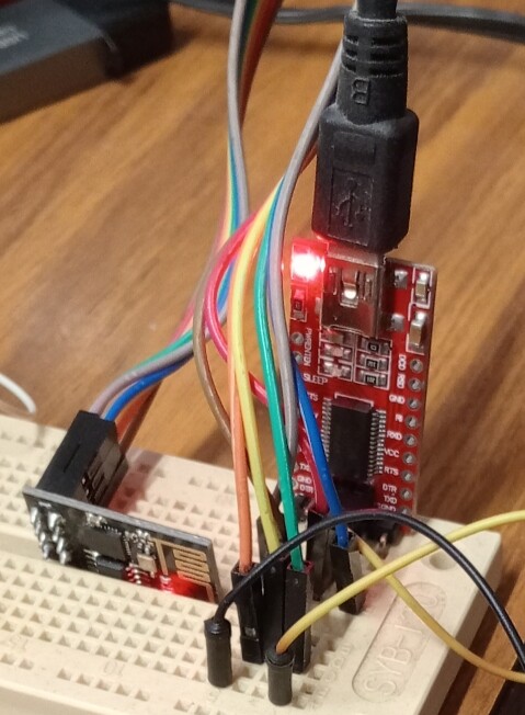
There is a solid red LED on both the FDTI232 and the ESP-01, suggesting that power is OK for both. I understand I should be seeing a blue LED on the ESP, next to the red one.
There seems to be some confusion about the wiring but I have removed the jumper GPIO 0 to ground.
I'm using stuff out of the spare parts bin. The ESP-01 just has to get network time once in setup, and should be entirely adequate - if I can just get it started.......
That's not enough current. You only get ~50mA worth from the FTDI. It is sourced through the internal 3.3 V regulator of the FT232R chip, which is not designed to supply power for external devices.
You need a more suitable power (and likely a capacitor to absorb peak demand when using the radio)
I didn't think I was doing anything out of the ordinary here. There are plenty of articles around using this same programmer. It just so happens that I am putting together a little PCB for a Pro Mini and ESP-01 with individual power. There is 480mA for the ESP, and guess I can adapt the FTDI into that.
The programmer is fine - the power not always adequate. With the radio off, the ESP-01 typically draws around 15 to 20 mA when idle, so you can be fine "programming" the module with the 50mA draw but for reliable Wi-Fi operation, especially during transmission peaks, it’s recommended to provide at least 250mA to 300 mA.
I think Wi-Fi is initialized and active by default at boot unless explicitly disabled ➜ running a basic blink sketch on an ESP-01, with the radio active but idle, typically draws around 70 to 90 mA during normal operation.
To enter programming mode, it's necessary to hold down the flash button while you click the reset button. You should see a single brief blink from the blue led. Then you can upload your code from the IDE.
After upload has completed, I think it's necessary to click reset again (without holding down flash button) to start your code running. You should see 2x brief blinks of the blue led.
To test that the ESP-01 is working and has adequate power, I recommend uploading the WiFi scan example code and checking serial monitor.
Good, but you need to reset the esp-01 after that to get your code running, I think. Or cycle the power.
The Pro Mini is 5v and I have dividers on Tx and the pin for ESP's CH-PD. It has its own 480mA supply and the ESP has a 500mA supply. Pro Mini is for 6x7seg LEDs under 7219s. I need the maximum range of brightness control, and this is probably stretching the friendship with my NODE MCU - even if it does have enough pins..
The job is a countdown to event timer for astrophotography, hence the NTP facility. There is a DS3231 on board, so I can abandon the ESP-01 if I have to but I would really like to use it.
I guess you figured out the answer but for the general discussion here, I think the pin is provided because in some situations — like custom interfacing circuits, logic-level translation, or small auxiliary functions — a modest 3.3 V source is useful.
That sounds a reasonable precaution. My code now is
#include <ESP8266WiFi.h>
void setup() {
pinMode(1, OUTPUT);
WiFi.mode(WIFI_OFF);
WiFi.forceSleepBegin();
delay(1);
}
void loop() {
digitalWrite(1, LOW); // Turn the LED on
delay(1000);
digitalWrite(1, HIGH); // Turn the LED off
delay(2000);
}
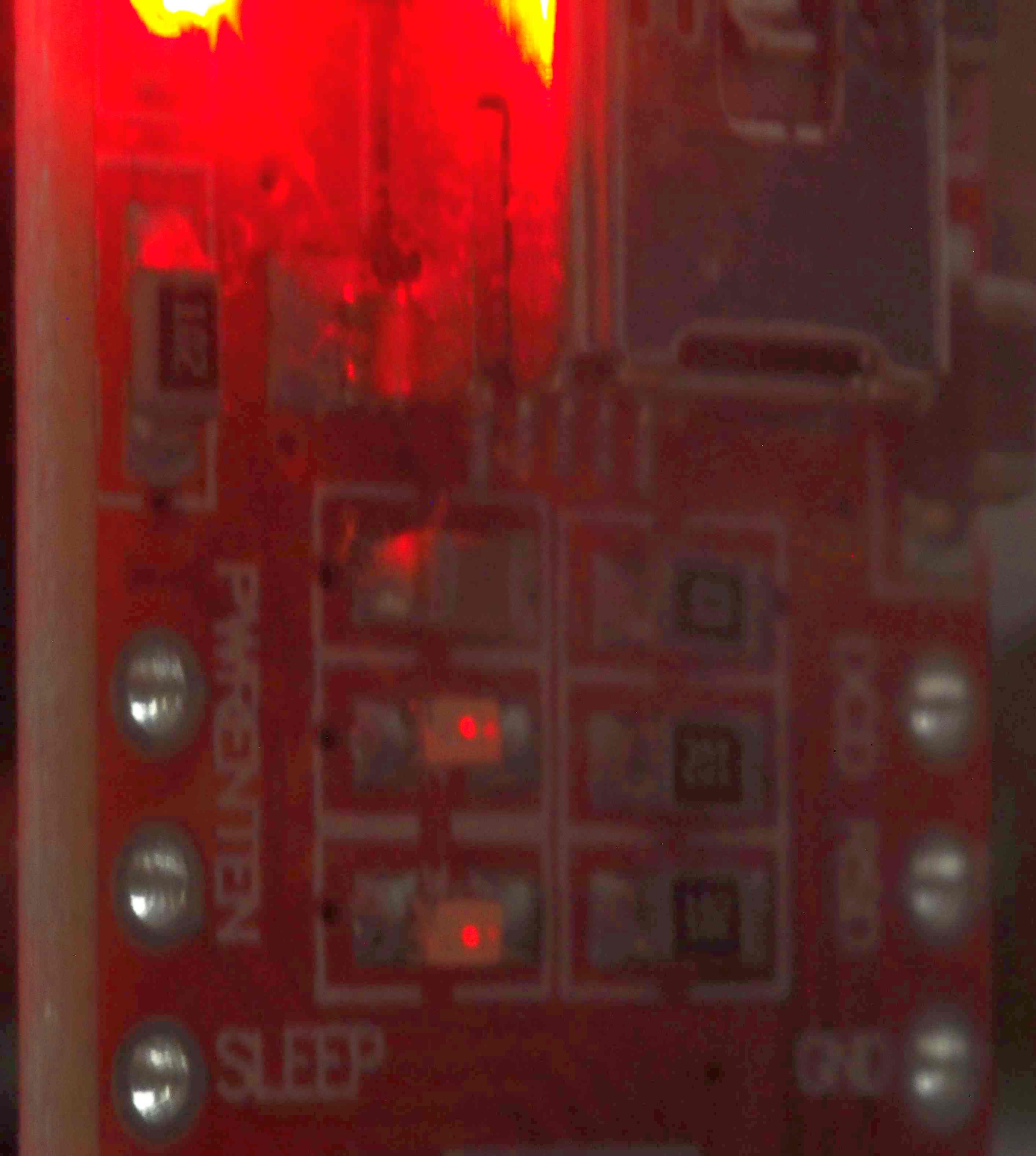
Still no joy. I guess it's all too fiddly and I need to put in switches following post#9. Now the sun has gone in I can see two little LEDs flashing on the programmer that I haven't seen before. They flash as long as CH-PD is on VCC.
You could use an HT16K33 chip for that. The ESP could control it directly over i2c bus. So the Pro Mini would not be needed.
This is confusing. There is an ESP-01 and a NodeMCU in your project? What do you mean by "stretching the friendship" of the NodeMCU? How does this affect the brightness of the display?
No, I don't think so. But you need to reset it, after you have disconnected gpio0 from ground, to get the uploaded code to run.
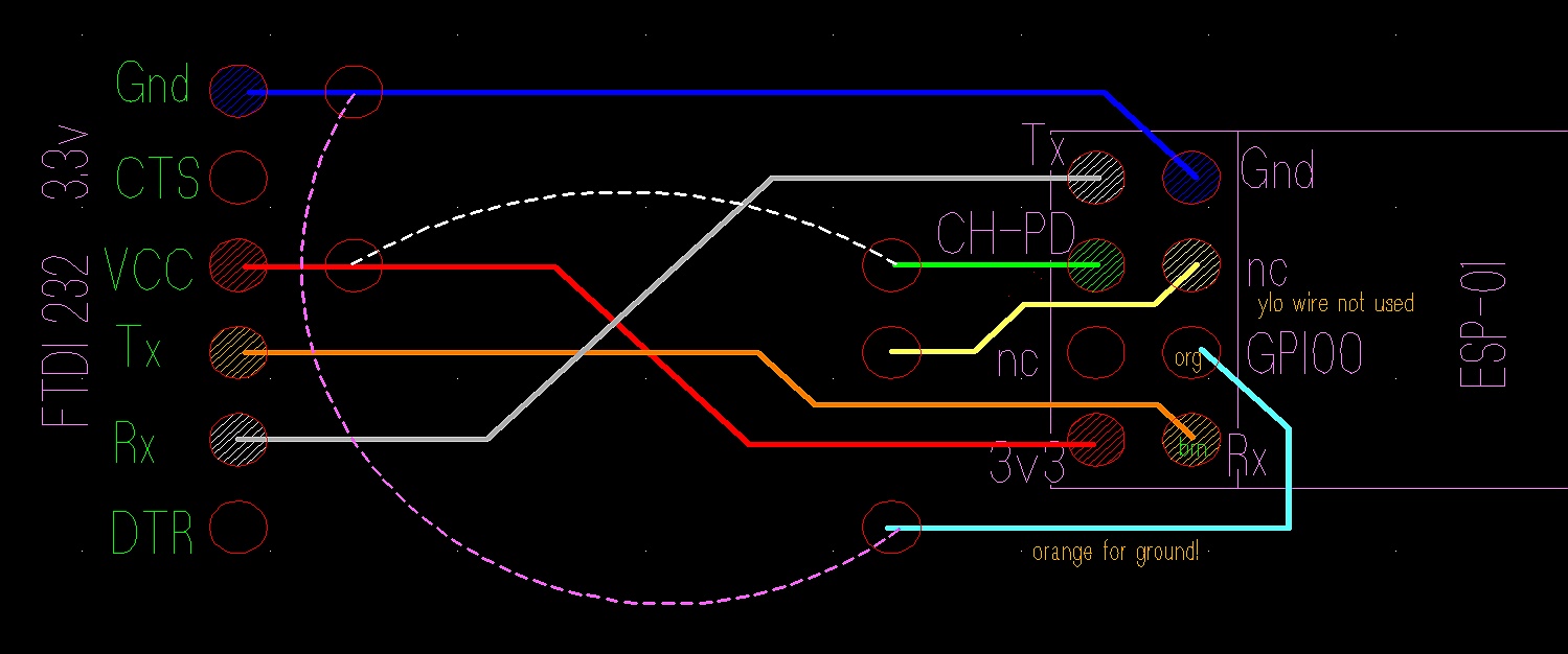
Look at the table at the bottom right in this diagram. It shows how the mode of the ESP is set at power-up/reset, based on the voltage levels of gpio0 & gpio2.
You want "serial programming" mode to upload your code from the IDE.
You want "boot from flash" mode to run the uploaded code.
So maybe you need to connect gpio2 to 3.3V also.
This doesn't stop you using gpio0 and gpio2 as the SDA & SCL pins of an i2c bus, to which many components can be connected like RTC, GPIO extenders, led display drivers...
Also check out the specs at the top right of the above and compare them to your Pro Mini...
All strapping pins on an ESP8266 respond to being pulled LOW or Free-Floating / HIGH. In other words, where it says in the table HIGH, Free-Floating is the same as long as they are not pulled LOW. Also not pulled LOW through an LED or transistor though. Hence the Builtin LED is active LOW, from Vcc -> Resistor -> GPIO.
It normally does a soft-reset afterwards and the code should run, though from a hardware point of view it will still be in upload mode. But to make sure, yes disconnect GPIO 0 from GND and reset, that should for sure get it to run in normal mode.
During upload, if the LED is on GPIO 1 (which it most likely is, boards with the LED on GPIO are extremely rare these days) you should see it lighting up and flashing a bit because the Serial tx is sending back a confirmation to tell it's ready for a new block of data to store.
If you get you multimeter out, you can confirm that the LED is actually connected to GPIO 1 (or GPIO 2)
The ESP-01 will need at least 100mA for normal operation without connecting to a WiFi network. If you have provided that, and you have successfully uploaded, it should just work, unless you may have an ESP8285. In that case upload will work, but the ESP-01 won't.
You can try setting the board selection to 'generic 8285' and assume that the LED is on GPIO 1 in that case.
I recall discussion years ago that ESP doesn't play that nice with LEDs, not enough volts and not enough current. I do have a NODE MCU but it is not used in this project, although I did consider it. I have the displays and the 7219s. I even have a PCB, so I don't want to change the hardware now. The only stuff I have had to buy are a couple of opto isolators. and a regulator.