I can't get my shift register to work. I've spent so long on this and have corrected quite a few problems, but now I'm sure the circuit is perfect, but still doesn't do anything at all (no LEDs turn on).
I'm following this tutorial, but have http://www.arduino.cc/en/Tutorial/ShiftOut.. I've gone through a load of different ones too (to a point where I know the 74hc595 pins off by heart) and have tried those ways also, but still to no avail.
I'm powering my arduino UNO through USB. current is flowing
I'm using 0.47 resistors (yellow), but have also tried 0.22 resistors (blue). I have tried 3 different shift registers, using pliers to pick them up.
When the circuit is on, my multimeter reads the leds as 001 when on the led setting.
I really can't figure it out, can someone please help.
We get this a lot here, where people say "I've followed this and done everything right, but it still doesn't work. What's the problem?". Unfortunately, we can't tell if that's all the information we're given.
Please post a photograph of your circuit clearly showing all connections, and the actual code you are using, not the code you think you're using. When posting code, post the entire sketch inside [ code][ /code] tags, and not just part of the sketch.
I'm using 0.47 resistors (yellow), but have also tried 0.22 resistors (blue). I have tried 3 different shift registers, using pliers to pick them up.
Hi, did you say 0 point 47 and 0 point 22 Ohm resistors.
I think you should be using 470 Ohm or 220 Ohm resistors.
Check their value with a multimeter please.
Are you building your circuit on the long version of protoboard, if so check you supply tracks. In some protoboards the long power tracks down the side have a break halfway down.
A copy of your sketch and circuit will help us all to find some solutions. A picture of the layout would be nice.
Sorry for asking for so much but it looks like its needed to help you.
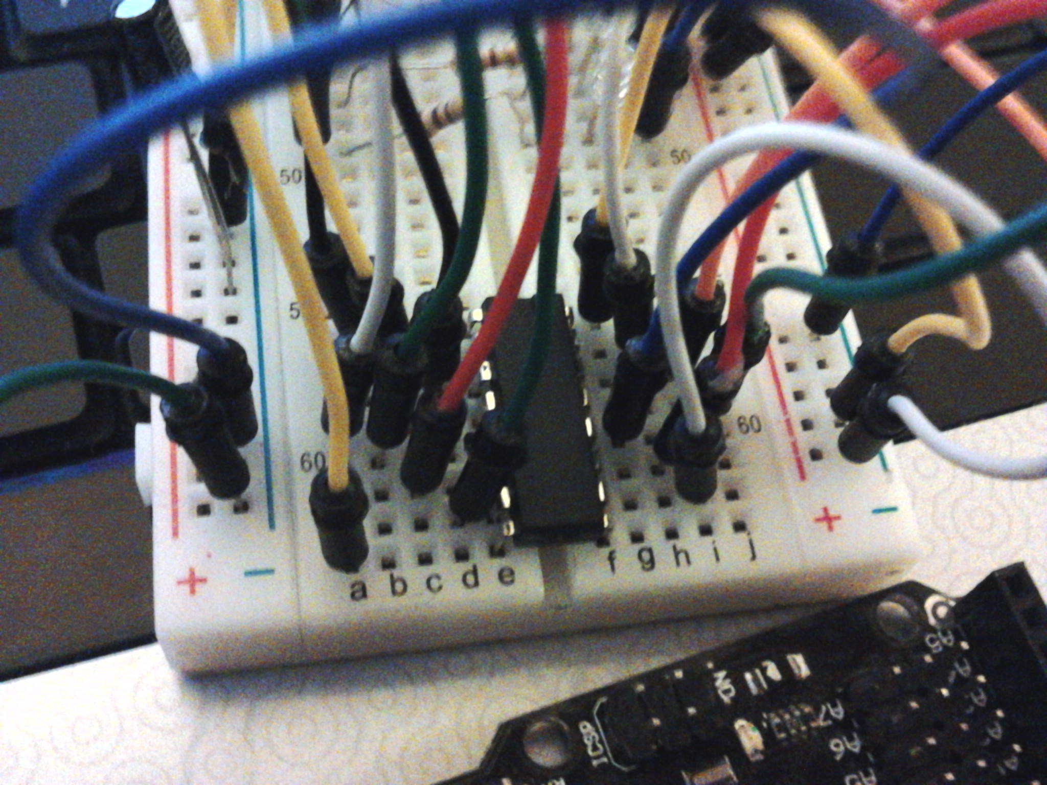
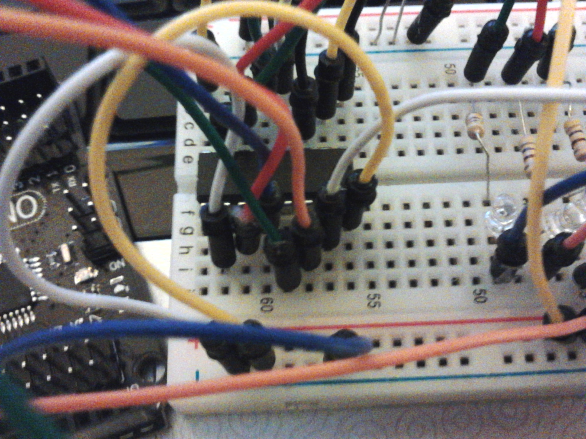
Here are some pics of the circuit. I tried it with and without the capacitor (I'm using a 10uf one, would that still work where only 1uf is needed?)
I have tried the LEDs going both positive to negative, and negative to positive
I am using this code:
//**************************************************************//
//  Name    : shiftOutCode, Hello World
//  Author  : Carlyn Maw,Tom Igoe, David A. Mellis
//  Date    : 25 Oct, 2006
//  Modified: 23 Mar 2010
//  Version : 2.0
//  Notes   : Code for using a 74HC595 Shift Register           //
//          : to count from 0 to 255
//****************************************************************

//Pin connected to ST_CP of 74HC595
int latchPin = 8;
//Pin connected to SH_CP of 74HC595
int clockPin = 12;
////Pin connected to DS of 74HC595
int dataPin = 11;


void setup() {
  //set pins to output so you can control the shift register
  pinMode(latchPin, OUTPUT);
  pinMode(clockPin, OUTPUT);
  pinMode(dataPin, OUTPUT);
}

void loop() {
  // count from 0 to 255 and display the number
  // on the LEDs
  for (int numberToDisplay = 0; numberToDisplay < 256; numberToDisplay++) {
    // take the latchPin low so
    // the LEDs don't change while you're sending in bits:
    digitalWrite(latchPin, LOW);
    // shift out the bits:
    shiftOut(dataPin, clockPin, MSBFIRST, numberToDisplay);

    //take the latch pin high so the LEDs will light up:
    digitalWrite(latchPin, HIGH);
    // pause before next value:
    delay(500);
  }
}
Kadoodle:
I tried it with and without the capacitor (I'm using a 10µf one, would that still work where only 1µf is needed?)
For the purpose of supply bypassing, 10µF instead of 1µF is absolutely fine, and 47µF fine too, given that these are nice compact electrolytic and possibly Tantalum. As electrolytic capacitors get larger however, they tend to have more internal inductance which impairs their high-frequency/ transient performance so that it is desirable to use a ceramic capacitor of 0.01µF to 0.1µF (or thereabouts) in parallel as well.
SMD devices with zero lead lengths are the best of course when you get to PCB stage.