Hi
I am trying to use the A0-A2 pins on an Arduino Pro Micro as digital outputs.
But no matter what I try, it doesn't work.
They are all just high level.
Here's a piece of code I tried.
#define CS A0
#define DC A1
#define RST A2


void toggleios(void)
{

  digitalWrite(CS,1);
  digitalWrite(DC,1);
  digitalWrite(RST,1);
  digitalWrite(16,1);
  delay(100);
  digitalWrite(CS,0);
  digitalWrite(DC,0);
  digitalWrite(RST,0);
  digitalWrite(16,0);
  delay(100);
}
void setup() {
  pinMode(CS,OUTPUT);
  pinMode(DC,OUTPUT);
  pinMode(RST,OUTPUT);
  pinMode(16,OUTPUT);
}

void loop() {
toggleios();
}
I have also tried using 18, 19 and 20 instead of A0, A1 and A2, same result.
Another strange thing is that when I run this code, pin 15 will toggle simultaneously with pin 16.
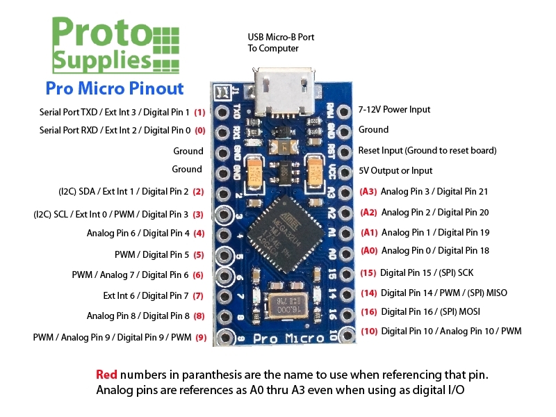
According to this Pro Micro pinout , analog pins A0, A1 and A2 are addressed as digital pins using Arduino pin numbers 18, 19 and 20.
Yes, I tried that too, same result.
I added that to the original post now for clarification. Thanks for pointing it out.
Maybe it's not good with 1,0 as output states.
I did not see pinMode() in your code, that is needed so the pins get initialized to the correct mode.
It's right there in setup
1 and 0 works fine, I have pin 16 as reference in the code and it works fine.
On the other hand I have tried some other code that used HIGH and LOW instead, same result.
Thomasx:
1 and 0 works fine,
You're here saying they "don't work", now they do?
1 Like
PaulRB
March 23, 2024, 11:05pm
9
How are you measuring that?
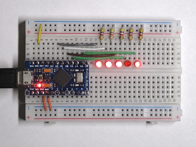
I just put a Pro Micro on a breadboard with your sketch and I'm not seeing anything unusual. LEDs on A0, A1, A2 and pin 16 are flashing, and the LED on pin 15 stays off.
1 Like
With an oscilloscope and a logic analyzer.
Please don't modify your original post. It makes the thread difficult to follow.
1 Like
van_der_decken:
I just put a Pro Micro on a breadboard with your sketch and I'm not seeing anything unusual. LEDs on A0, A1, A2 and pin 16 are flashing, and the LED on pin 15 stays off.
@van_der_decken
So my Pro micro is not fully functional then. Too bad, it's new.
Thanks for helping out with this!
This is what I saw (and expected to):
Left to right: A2, A1, A0, 15, 16.
1 Like
I happened to have two of these boards, so I tried the other one, also brand new, it's exactly the same with that one.
The both looks exactly like your board @van_der_decken , the pcb routing looks the same too.
I guess the conclusion has to be that I have gotten two bad boards.
Thomasx:
I happened to have two of these boards, so I tried the other one, also brand new, it's exactly the same with that one.
Do the 'pins' in question work as Inputs (digital or analog) ?
Taking a deeper dive into the 32U4 datasheet I notice that the problematic pins are also used for the JTAG interface, and if this is enabled, these pin won't work as digital outputs. I have a hunch the JTAG interface is enabled on my devices.
It seems I must use an AVR ISP programmer to fix that. I will see if I can manage that.
This is the best AVR ISP programmer I've ever used, which also doubles as a USB-serial converter. Comes with a nice GUI that allows you to control various options, and works well with both 5V and 3.3V MCUs.
This in-system programmer can be used to program AVR microcontrollers and AVR-based controller boards, such as our A-Star 328PB Micro, Orangutan robot controllers, and the 3pi robot. The programmer emulates an STK500 on a virtual serial port, making...
YES YES YES!
Lucky me I had an old Atmel-ICE tucked away in a drawer. Worked perfectly to connect to the Pro Micro JTAG interface.
Sure JTAG was enabled. So I disabled it, and now the IO's works as expected!
Thanks everyone for your efforts in helping me! It's highly appreciated!
system
September 20, 2024, 2:56pm
20
This topic was automatically closed 180 days after the last reply. New replies are no longer allowed.
