I have made a timer clock based on CD4026 IC.
The clock is working normally as it should be.
The problem i am facing is that,
On initial start (supplying power), the third CD4026 IC from right (for minutes counting) jumps from '0' to '8' and then it continues to work normally.
So, I want to know how can I eliminate this random jump at starting, so that the clock starts at '0'.
Also, i am having problem in resetting the whole clock once it starts counting. All the CD4026 have to be resetted individually and cannot be reset together, as on doing that the normal counting also gets affected.
Any tips/help are welcome.
have included the CD4026 pinout, timer schematic and PCB design for your reference.
Hey this really is the wrong forum for this. There’s no Arduino in your project.
This looks like it counts to 99.99.99, if this is what you intended then it’s really Just a decimal counter? I would not call that minutes and hours in that case, it would be incorrect. It would make more sense as a 99 hr 59 min 59 sec format.
I see a few issues just to get you started, you don’t need all those resistors R9-R14 with your current counting method. Should be one and try 10k.
555 is not great for accuracy if you need any accuracy with your timer.
To reset all the counters at one time, put in a momentary switch to all the resets to VCC.
Try this and see what happens on reset for your start up issue.
Your schematic is difficult to follow and I doubt someone will spend the time to redraw it to make sense of it.
A system with multiple flip-flops like this one
needs a 'power on reset' circuit. The idea is
to hold all the counters in reset mode
until the power supply and clock stabilize.
Then everything starts from a know condition.
Herb
That is an amazing hard wired clock (count up timer) . Your own design?
I guess it is not the point, but the component count could have been significantly reduced by using a micro controller and a display driver chip.
I’m surprised that the start up error is so consistent. For the minutes (that is not tens of minutes) counter to display the 8 as you have said , the tens of seconds counter must have attempted to display a 6 ( detected by segments E, F and G , which would incidentally also have detected an 8 ) eight times.
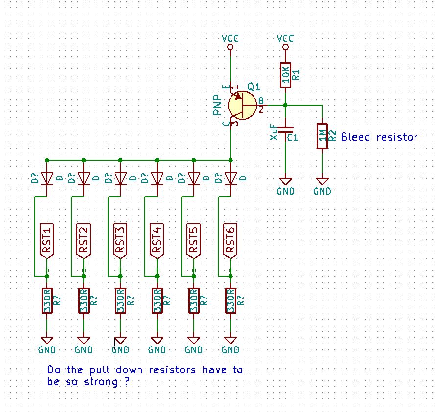
I’d probably be thinking about a transistor on the high side with 6 diodes to pull all the resets high for a clean start , as an “add on” without interfering too much with the existing logic, but such ideas need good testing first.
I have used three NPN transistor to make a 3-input-1-output AND gate. This way when the second timer reaches 60 the second IC is reset and third IC gets a high pulse. Similarly for 60 minutes and 24 hours.
So it's not a 99:99:99 timer but its a 23:59:59 timer.
the R9-R14 resistors are connected to reset pin of each IC and keep the reset pin pulled low, so when the reset pin gets high signal it resets the counter of that IC. I cannot have only one resistor for all IC as then all the IC will get reset every 60 seconds.
Will try to make simpler and easier to follow schematics in future.
wolframore:
Hey this really is the wrong forum for this. There’s no Arduino in your project.
This looks like it counts to 99.99.99, if this is what you intended then it’s really Just a decimal counter? I would not call that minutes and hours in that case, it would be incorrect. It would make more sense as a 99 hr 59 min 59 sec format.
I see a few issues just to get you started, you don’t need all those resistors R9-R14 with your current counting method. Should be one and try 10k.
555 is not great for accuracy if you need any accuracy with your timer.
To reset all the counters at one time, put in a momentary switch to all the resets to VCC.
Try this and see what happens on reset for your start up issue.
Your schematic is difficult to follow and I doubt someone will spend the time to redraw it to make sense of it.
Thanks for the appreciation. Idea is not mine but the schematic design is mine.
I agree using a uC and display driver would have been much easier, but then that was the whole point of using basic components to make the timer clock.
Regarding the error, on prototype board there was no such error and thus i fabricated the PCB and now i have this error.
Also can you diagramatically show me what you meant by
I’d probably be thinking about a transistor on the high side with 6 diodes to pull all the resets high for a clean start , as an “add on” without interfering too much
6v6gt:
That is an amazing hard wired clock (count up timer) . Your own design?
I guess it is not the point, but the component count could have been significantly reduced by using a micro controller and a display driver chip.
I’m surprised that the start up error is so consistent. For the minutes (that is not tens of minutes) counter to display the 8 as you have said , the tens of seconds counter must have attempted to display a 6 ( detected by segments E, F and G , which would incidentally also have detected an 8 ) eight times.
I’d probably be thinking about a transistor on the high side with 6 diodes to pull all the resets high for a clean start , as an “add on” without interfering too much with the existing logic, but such ideas need good testing first.
This is a suggestion for forcing a clean reset. The switch could be replaced by a transistor, say an PNP with a 10K pullup resistor. Grounding the base temporarily would force a complete reset.
herbschwarz:
To reset on a '6' output, you only have to
look at the c & e segments, right? (That may
simplify things.)
Herb
That will reset on zero also.
truth table included.
6v6gt:
This is a suggestion for forcing a clean reset. The switch could be replaced by a transistor, say an PNP with a 10K pullup resistor. Grounding the base temporarily would force a complete reset.
This could work, but can we add a capacitor-resistor network (RC network - may be 100nf with 47k) instead of the switch, so it will take some time to raise the voltage of the capacitor thru resistor at startup and as soon as the capacitor is charged it will reset all the IC to zero. don't know i may be wrong.