Hey there,
I'm creating an Arduino UNO battery shield. I want to be able to program the Arduino and charge the battery from the same port, thus I had to add that onto the board, as well as the CH340C through which I wanted to program the Arduino.
When uploading a sketch, the RX LED blinks three times and then continues to blink a couple of times with a much longer delay (of course the sketch upload is unsuccessful). Furthermore, if the sketch on Arduino is outputting anything on the Serial monitor, the RX LED is on as expected. If I try to upload a sketch through the shield, absolutely nothing happens. I suspected the chip didn't reset the Arduino so I tried to reset it manually with a button when uploading, but that didn't help either. I also tried changing the CH340C in case it was faulty and came out empty-handed.
I haven't got the foggiest clue what could be wrong. Please help!
This bit doesn't look right. The CH340 cannot see or create an actual logic LOW level this way.
I'd start by removing the LEDs or R8 + R9 and bridging R10 and R11 with a jumper wire, then try again.
Also, the DTR line (not the DTR pin on the CH340G, I mean the net after the 100nF cap) is named a bit confusingly; I assume it connects to the microcontroller's RST.
Have you verified you're not confusing RX and TX. TX from the CH340 should go to RX on the microcontroller and vice versa.
I tried removing the LEDs and bridging the R10 and R11 and it didn't help.
Yes, you are correct. The DTR connects to RST pin of Arduino.
I have verified that RX and TX are correctly connected. I even tried connecting the shield with jumper wires and switched TX and RX. That didn't allow me to upload sketch, but I was able to receive a signal on Serial monitor.
The confusing part is that I have used this schematic a dozen of times and it worked. So why doesn't it now
So you did/do have TX and RX swapped, then? If swapping them with jumper wires gives you correct Serial monitor output, surely, there's a PCB routing error.
Anyway, this reduces the problem to either the TX or the reset circuit. Have you tried manually resetting the microcontroller at the start of a code upload to see if that helps?
If you have an oscilloscope, see what happens on (CH340) TX if you send a continuous stream of data to the board and trace that signal from the CH340 all the way down to the microcontroller.
Well no I didn't have them swapped. When I use USB to TTL programmer I connect it correctly and upload a sketch without any issues, this way I can't see what's on the Serial monitor either.
Try uploading a sketch to the UNO that uses bidirectional UART communications (both TX and RX) to verify both directions work on your CH340 circuit. That way you can at least track down whether the problem is associated with TX or the reset circuit.
The 'scope advice also still stands; since you didn't respond to that, I'll assume you don't have a 'scope. If not, consider purchasing one if you intend to do more projects; it makes life a whole lot easier.
I considered that, John, but at least theoretically, it should work out - and there's the observation that it does work OK with an external USB-TTL programmer that hooks into the same pin headers on the UNO.
Consider that the TX and RX lines on the UNO are connected through 1k between the 8U2 and the target ATMega. This is also why I suggested bridging the 1k series resistors on OP's own board, because they would create a voltage divider, making the LOW level 0.5xVcc - which would be a problem. He says he bridged them (and removed the problematic circuitry involving the LEDs, which made matters worse) and the problem persists, which I hadn't anticipated.
Turns out that the RX and TX was indeed connected incorrectly. I switched them in the schematic twice, that's as if I did nothing. So I used the jumper wires and connected it to the Arduino correctly that way.
Now I'm able to see what the Arduino is sending on the Serial monitor, but still can't program it. When I tried a bidirectional communication sketch I was able to receive, but wasn't able to send anything. When I tried it with the port of the Arduino it worked fine. I own an oscilloscope, but not an expensive one so operating with it is kind of difficult. I tried to avoid using it. Turns out I will have to
Okay, well, things are starting to get a little more clear, which is good.
I hear you on cheap scopes sometimes being annoying to use. Still, it's worth a try in this case. Set up your scope to observe a 'healthy' UART signal first and then take those settings to your problematic TX line.
I would suggest leaving the scope on the shelf and investing ~$15 in an inexpensive logic analyzer. They will capture and decode many protocols - I use mine much more that my expensive scope for debugging serial, I2C, SPI ...
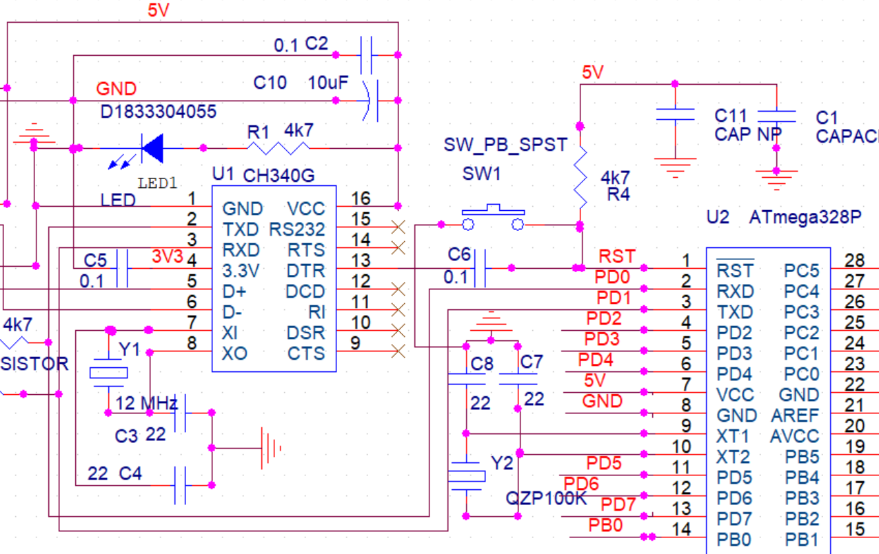
You are missing 12 MHz crystal (Fig-1, across pin-7 and 8) for CH340G chip. You must connect 12 MHz crystal and 22 pF capacitors at each leg of the crystal (Fig-2).
I didn't either until I was looking at the underside of some Nanos and noticed that some had crystals, some didn't, and they all worked anyhow. Which prompted me to take a look at the datasheet where I got the "a-ha!" moment.
And I am wandering why is the G-version with external crystal when the C-verson is fine with internal crystal? For C-version, I am getting all those Chinese Language data sheets that have made my life difficult to know the value of the internal crystal.
I suppose it's a tradeoff between stability/accuracy and parts count. The C version (and a couple of others) probably run off an internal R/C oscillator, which implies they're probably less temperature stable.
However, we could already infer that the missing (unneeded) crystal wasn't the problem since the CH340 is apparently enumerated fine by the host OS and OP can get RX through it to his console. Without a functioning oscillator, the CH340 wouldn't have synced to 12MHz USB.