Arduino Uno and the Inter-Integrated Circuit protocol (i2c /TWI) from pins 4 and 5.
2 x Hygropchip HYT-221
2 x 2k2 Ohm resistors as pull-ups
Vcc = 5v
wire library in arduino 1.0.5-r2
Reading data from one sensor is fine however as they have the same address by default i need to change one of the addresses on the sensor. this is explained in the tech spec linked above however I've watched many youtube videos and read as many forum posts and tutorials as i can manage yet it's still over my head.
this is some of the code I've tried, Ive attached an image to this post which is just a screen shot of some of the tech spec which runs through how to change the address on a sensor. I've tried to convert their instructions into code however i cannot understand how to debug or retrieve errors from the sensor in i2c so any help in that way would be most appreciated.
please let me know if more info is required,
cheers
Joel
On this page : ub8优游登录入口-ub8优游登录入口手机版下载 - 优游国际官网
Click on the "Documentation". There is a minimal Arduino example code, but not to change I2C address.
According to the Application Note page 15, the sensor has to be set into "command mode". You need to start communicating with it within 10ms after power-up-reset. I can not find how long the reset takes after power up.
Do you have a Arduino output pin connected to the power ?
I read about the sequence to change I2C address, but it is not very clear to me when to read and when to write.
Thanks for your reply and for directing me back to the website documentation, I had completely forgotten about that and it seems to hint at clearing up their explanation in the Application Note. I will have a proper read through and try and decipher the change of address sequence again.
How do you interpret the power-up-reset. Should i simply load the program onto the arduino and then press reset and this will run the program after the reset? Or do you think i should turn off power to it completely by pulling out the usb?
The code I've written is trying to mimic the steps below (link to the document above)
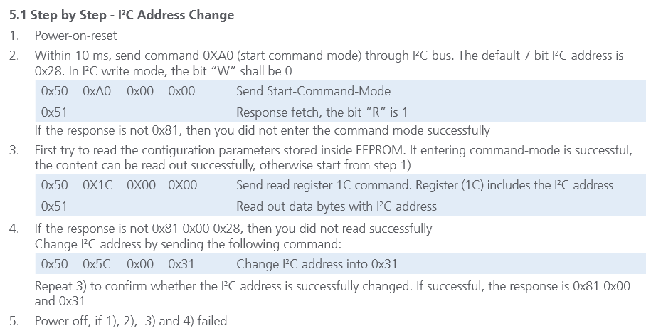
5.1 Step by Step - I2C Address Change
Power-on-reset
Within 10 ms, send command 0XA0 (start command mode) through I2C bus. The default 7 bit I2C address is 0x28. In I2C write mode, the bit “W” shall be 0
0x50 0xA0 0x00 0x00 Send Start-Command-Mode
0x51 Response fetch, the bit “R” is 1
If the response is not 0x81, then you did not enter the command mode successfully
First try to read the configuration parameters stored inside EEPROM. If entering command-mode is successful,
the content can be read out successfully, otherwise start from step 1)
0x50 0X1C 0X00 0X00 Send read register 1C command. Register (1C) includes the I2C address
0x51 Read out data bytes with I2C address
If the response is not 0x81 0x00 0x28, then you did not read successfully
Change I2C address by sending the following command:
0x50 0x5C 0x00 0x31 Change I2C address into 0x31
Repeat 3) to confirm whether the I2C address is successfully changed. If successful, the response is 0x81 0x00 and 0x31
5.Power-off, if 1), 2), 3) and 4) failed
In the above steps, 2. says "Response Fetch, the bit "R" is 1" can anyone shed some light on what this means? plus the part below, "if the response is not 0x81, then you did not enter the command mode successfully" does anyone know how i could go about finding the response from the sensor using the wire library and if its possible?
For some reason i wasn't notified or missed the email that you had replied, i'd checked the German site and that got me a little closer and i started messing around with his Python code, however it wasn't doing what i wanted and i haven't looked into further.
But the code you sent now works a charm, thank you soooo much. It works perfectly, i've been stuck on this for weeks and this has brightened my week, i'm truly very happy can i send you a bottle of wine as a thanks?
I didn't trust the suggested Sketch. So I wrote a new one.
It checks also for return codes from sensor and the sketch writes back also the original high byte of modified address in sensor. I read the EEPROM data with command 0x1C from address 0x1C and get a highbyte and a lowbyte. I write it back with command 0x5C to address 0x1C keeping the orginal value of highbyte and just modifying the lowbyte by the new sensor address.
I have powered on the sensor with a power switch after I've got the message from my Sketch in serial port window. So I can use also a Gertboard and a Rasperry Pi which takes a longer time to start up.
In the Sketch I've just used the original I2C address of sensor (e.g. 0x28) it it will be translated automatically into 0x50 and 0x51 by write and read commands. So I don't have to take care about this transformed addresses.
Thank you for this sketch, Ive also been able to assign different i2c addresses thanks to this. Ive made a diagram of how the sensor should be connected to the Arduino uno in order for this program to work for people looking at this forum in the future.
I've tried what was proposed here but nothing seems to work.
I've connected the sensor as described, I can measure correctly but I cannot get the 0x81 byte that's supposed to arrive after entering Command mode.
I even tried (as the application note proposes) to lower the I2C frequency.
From what I understood from the application note, you're supposed to send an 0x50 byte to begin writing to the sensor. However, the code posted here does not do that. How is that possible? Wire.beginTransmission does not write anything to I2C, so it's not replacing the sending of 0x50. Same goes for endTransmission.
PS: managed to get it to work, I was wasting time after power-up printing on Serial (forgot how slow Serial is). Also, writing 0x50 seems like is not needed - cannot figure out why, maybe something inside twi.c makes up for it?
PS2: attached sketch with more functions/tests/options. Can change i2c speed, asks for new address and does multiple tests. Overkill, really, but maybe it helps someone. (: