I am working on guitar MIDI foot-switch that have several pages (i.e. remapping on the buttons based for each pages).
I would like to use a DPDT switch to play a dual function based on the page : In some cases, I want the switch to act on a TS audio jack and other times the same switch should trigger the PIN D8 on the Arduino Micro.
A PIN on the Arduino (D7) would be used to decide how the switch works.
The DPDT would have to do the following :
Page 1 - Control an audio TS jack that requires a normaly-closed loop (the device hooked to the TRS is a RC-5 Boss that work with such setup )
Page 2 - Send a MIDI command to TX when the PIN D8 is pressed using the normally open side of the DPDT (i.e. when the DPDT is pressed, D8 read it and sent via the TX port)
To do so, I am hoping to use transistors to toggle the DPDT function in the following manner
When the D7 is OFF,
The transistor 2 is OFF and the TS is normally closed unless I press the DPDT to open that TS loop
The transistor 1 is OFF and the D8 switch is not responding to the DPDT
When D7 is ON
The transistor 2 is ON, and no matter the position of the DPDT, the TS remains in a close loop
The transistor 1 is ON and a press on the DPDT triggers D8 which is turn send a MIDI command on TX.
I have a very limited experience in electronic so I am not 100% sure this is feasible at all. I sketched the circuit below and wanted to get your advice on its viability.
Does that seems like this would do the trick? What transistor should I use (N or P?) and what value of resistor should I used?
Thanks for reading
Sorry, can't read the light blue pin designations. Why not use black having the highest kontrast?
Feeing the transistor bases without resistor is not good.
Basically that's not the way to use transistors.
While there are three basic ways to configure a transistor, then 90% of the time we use them in what is called a common emitter configuration.
This is where the emitter is connected to the ground and the base is connected through a series resistor to a digital output of an Arduino. Then when the Arduino output is low, the transistor is off. When the Arduino output is high, current flows through the resistor and turns the transistor on. What this means is than current will then flow from the collector of the transistor to the emitter.
Between the collector and the power supply is the load.
It is not clear what you want this transistor to do. You only show it going to a switch contact on a relay, or at least that is the way I read it.
I was hoping to use Transistor 1 to disable the foot switch so that nothing happens to D8 when the user push the foot-switch and the transistor 2 is not letting current between its emitter and collector.
The end goal is to have the switch to either command the D8 on the Arduino OR the TS Audi jack but not both at the same time.
I know that very not easy to read, I don't know how to change it in the program I used.
Basically the labels on the Arduino are D8 D7 5V from the bottom left then clockwise with 5V at 6 o'clcok
I added the resistor you suggested
Sorry but I am just not understanding that circuit and what you think it will do.
What do you mean by the TS loop?
As far as I can see transistor T2 is a PNP transistor and T1 is an NPN transistor do you mean that or is it a mistake?
I can't see why you need a transistor at all. The jack socket has its right channel connected to ground ( which is normally on the sleeve ) will mute the right channel at best and at worst damage the output stage of the right channel driver.
Anyway you can't route audio with just a transistor because audio is an AC signal symmetrical about ground.
I can only suggest you try that circuit and see if it does what you want, but I doubt it will.
Maybe if you could include more of your circuitry in your schematic we could see what we are dealing with. I am sure you could just do it all in software.
Transistor 2 is a PNP and will require the base to be more negative than the emitter in order to turn on so it will not function as it is shown on that schematic.
As mentioned in my post, I really have limited knowledge of electronic so from the comments I gather this will not work as I am was hoping.
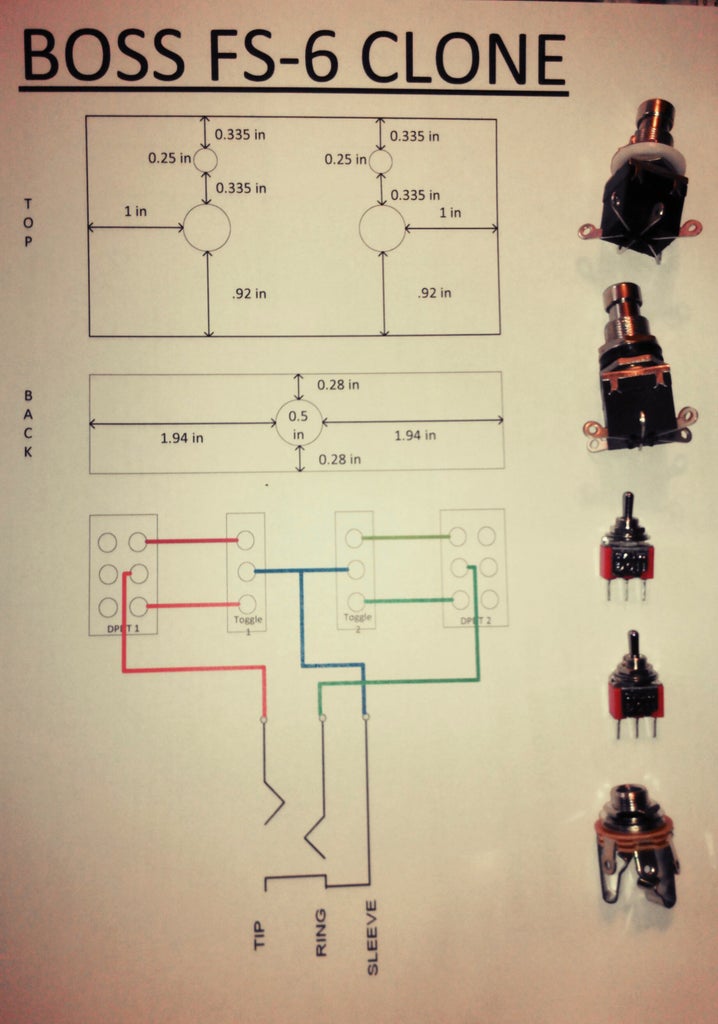
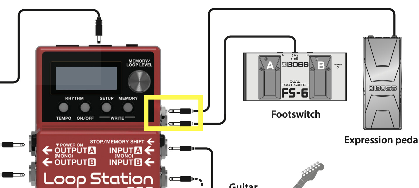
The jack socket is plugged to a Boss RC-5 looper to control the looper. Here is how the footswitch is supposed to work for a TRS cable and two buttons :
Note that this circuit has also a switch to change the polarity but I don't care about that.
In my case, I am interested in only one of the channel (i.e using a mono cable) and using 1 button,
Now, I would like to also use the button to trigger the PIN D8 of the Arduino.
However, I want to be able to decide via the Arduino if the button control the jack or the pin D8.
I was hoping using a transistor hook to D7 would allow me to toggle what the switch control (D7 or jack). Maybe there is another way to do what I am trying to do ??
OK I have downloaded the Boss RC-5 looper user manual. So can you tell me which of the many jack inputs you want to connect this peddle to?
Now your choice of the word "buttons" is confusing here, do you mean the foot switches?
Again this puzzled me:-
What do you mean by polarity here, and what does it do to the looper?
Yes I would think so. It sounds like you want to use one or two relays to do the switching and use the Arduino to control them. This isolates the switching and allows the software to act exactly like you want.
Are you familiar with relays and how they work?
The original Boss FS foot-switch have a polarity switch at the back (see photo above). The switch toggle the foot-switch between Normally-Close and Normally-Open. I don't need that what I am building (always Normally-Close is what I need - unless I press the foot switch the tip and sleeve are connected)
The footswitch I am using is a DPDT (Double Throw Double Pole). So I am hoping to create a Normally-Close circuit for the RC5 pedal and using the same DPDT,create a Normaly - Open circuit to trigger D8 on the Arduino. D7 on the Arduino will be used to toggle between what the DTDP does
I am not familiar with relays (only use that one on my motorcycle when I had to change the horn).
I wrongly thought I could use transistors for this project. So I will look up the relays and post a new circuit.
You might be able to, but a lot depends on what the circuit is inside the Looper Station. So unless you can obtain a schematic to that, then it is much better to use relays. They have the advantage that you don't need to care about what this circuit inside the Looper Station actually is, they will work no matter what it is.
In fact you will probably need a transistor to switch a relay coil from the signal you get from an Arduino.
The way I see it you would connect the single function foot pedal button to an Arduino input. Then an Arduino output would switch the relay coil of the relay whos contacts are wired like the foot button would be.
Then the code would just be like a loop that would control the relay as the foot switch was seen to be open or closed.
This might not seem much different, but the point is that when you wanted to over ride what the foot switch was doing you could by just software. So that only if something was set in the software would the relay follow the foot switch. If it were not set then the relay would not follow the foot switch but set it to the state you wanted and send a MIDI message like you want.
The NC side of the relay is hook to the DPDT switch to trigger the TS signal of the RC-5 pedal. That signal is OPEN only when D7 is LOW and the DPDT pressed otherwise it is NC.
The NO side of the relay is hook to the DPDT switch to allow a HIGH to be sent to D8. That side of the circuit is only sending a HIGH when D7 is HIGH and the DPDT pressed. Otherwise D8 is LOW
D8 is sending a MIDI signal via TX.
-The relay prevents both TS and MIDI command to be sent at the same time when the DPDT is pressed.
I think that would look like this ???? But I am really not sure about the 5V and relay connections or if extra resistors are needed.
No you can't use D8 to send MIDI data if it is controlling a relay, use another pin to control the relay or to send MIDI.
Again not quite. The foot switch should be connected to an Arduino input only, so that the Arduino can read its state. Configure that input as an INPUT_PULLUP mode. As it is the Foot switch will short out the Arduino power supply. Not a good idea.
The TS cable should only be connected to the relay contacts. The relay driving is fine.
The other pole of the foot switch should not be connected at all to anything.
The foot switch will trigger an input of the Arduino only. Then, on the software side, I either send the MIDI command via TX or trigger the transistor via another Arduino Pin to open the relay so it acts like a switch for the TS cable.
That's very different that what I had in mind but I like that approach.
I think the circuit below is what you are saying :
In that case the foot-switch doesn't need a DTDP.
Could I have use the transistor to act as a relay ? So basically have the TS cable directly into the transistor ?
Correct, but robust foot switches come like that, at least all the ones I have seen.
I would wire the switch S2 the other way round. That is the switch is connected from D6 to ground, and the other end of the resistor is connected to +5V.
Yes that is the idea.
Now you say you want to send MIDI through Pin 8, how are you going to do that then? I am assuming that seeing you are using an Arduino Micro as you are using the USB connection to send MIDI, is this correct?
So what do you have that determines if you send MIDI or use the foot switch to control the connection between the right and sleeve? At the moment this can determined by the switch S2, but do you have another idea as to what would determine this?
No, as I said to know if that would work we would need to see the circuit inside the Looper, with a realy you don't need to know and it is all isolated.
The MIDI command is actually sent via the TX port to a DIN plug on the pedalboard. . What I meant is happens when D8 is HIGH.
As for the USB, I am using it to simulate a keyboard command so the pedalboard can be used to play/stop YouTube which is very useful when you learn a new song.
The pedalboard I am building has 10 foot-switches on it, one of them is use to change "pages". That is when pressed, the 9 other foot-switch are remapped to another MIDI or keyboard command. The idea is that one of the page will remap one of the switches to send a TS command via the relay.
My project is based on the following idea :
I will probably post the code and circuit once I am done with this project. So far it works great but I needed to add this TS jack to be able to also control the RC-5.