Perhaps there is already a finished product or IC that does exactly this, but I may not be using the correct terms for my search...
I want to take a linear 5v signal and modify the slope and offset of the signal. For example if I have a pressure sensor that outputs a voltage signal from the following equation:
V_out = 5*(Psi)/58
Where V_out is the signal output, Psi is the sender's absolute pressure reading.
But my display/gauge is expecting an input of:
PSI = 14.5*(V_in) - 7.25
Where PSI is the displayed value, and V_in is the voltage the the gauge sees from the sending unit.
Clearly these are not inverse functions so I will not get an identical mapping from Psi (actual) to PSI (displayed). I know how to algebraically convert one to the other, but I do not know the electronics/components needed to do so.
I know the Arduino cannot output an analog signal, but it does do digital PWM, then there are other IC's that convert the arduino digital to analog. But that feels a bit overkill.
Is there a single IC or other compact finished product (programmable via code, or by using a variable resistor/knob/buttons etc...) that can do this reliably with reasonable accuracy?
I can see how this would change the slope (amplification) but I am not sure about how I could change offset. For example add one volt across the board.
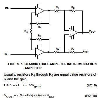
There is one thing I cannot seem to wrap my head around. From the following Equations...
Gain=(1+2*R/R_gain) ****Means Gain is a Constant
V_out = ([IN+] - [IN-])*Gain + V_ref
Since the Gain appears to be a constant set by precision/high accuracy resistors, it appears that Gain is definitely a constant.
I wanted to be sure of the remaining variable assignments:
[IN+]= input from the signal --- In other words, the 0v-5v linear signal output I want to adjust
[IN-] = signal ground --- The common sensor ground
V_ref=constant for the offset --- some constant (probably VERY small voltage)
V_out = New adjusted signal output, the signal I want my gauge to see.
How can I most accurately/repeatably set V_ref? Voltage divider? Small switching buck converter? Other?
Lastly are there any restrictions on the above that I may have missed? Such as V_ref must be some minimum value compared to [IN+]? or V_out must be less than [IN+]?
x being the reading of the analog input
val being what you want to display.
in_min is the lowest value for your analog input
in_max is the highest value for your analog input
out_min is the lowest display desired
out_max is the highest display desired
In my code I have low calibration, high calibration, low span and high span, reading the analog input, the display value is what ever I want it to be whether it be pounds, ounces, density or pH.
Dave,
Thanks for that MIT link. Some helpful reading for sure! If I do go that route, that documentation should be sufficient to get me making stuff. It is very thorough.
NASA,
From your response, if I understand it correctly, I may not have been clear on what I am setting out to accomplish.
If I were to go the Arduino + ADS1115 route, wouldn't I be looking at a DAC (Digital to Analog Converter) instead of the suggested ADC (Analog to Digital Converter)?
If I were to implement an arduino, I think I would go the route of:
Sensor v_out -----> Arduino analog read pin ----> Math/conversion equation ---> PWM digital out ----->DAC -----> Analog converted v_out -----> gauge
It is nice to know there is a turn key solution with some decent documentation, it should also be easy to adjust/program. Looks like I want the MCP4725 Breakout Board - 12-Bit DAC w/I2C Interface instead.
aarg:
It's too easy to do with op amps. You only need two, you can get a dual package like TL081.
I do not have the background knowledge to work off of that tip alone. I could probably piece something together, but I will be using the diagram and notes similar to what I posted in post #4. (the ones I posted actually call for instrumentation amplifiers, not that in know the real difference between the two since the diagram symbols are the same...)
I trust you that it probably is too easy to do for you. Skimming the data sheet, I only see extensive application notes for frequency alteration, as well as signal inversion. I did not see any slope+offset applications, such info would make it moderately easy for me.
I realize an op amp is an op amp... but from the documentation I have found, I do not understand enough to use an op amp (or a pair) to achieve what I desire.
Not sure what a "stable Vref" is in this link. There is no V_ref on the sensor I am reading. Just a ground and a signal that ranges from about 0v to 5v.