Hello
I have a differential analog signal with voltage limits of -4/4 V. My aim is to read the signal via the analog input from the Arduino but I’m struggling with the conversion to single ended input (0 - 5V) (my idea was a differential amplifier).
I’m relatively new to the subject and not entire sure if that’s the right way.
Did you find this thread?
You could use an RS232 receive IC there are many available. Personally, I would use something like an LM358 and connect the signal to each input via two 27K resistors. If your logic is reversed, simply swap the + and - connections to the op-amp. Try this approach and see if it helps. Also, use 5V instead of 12V.

The outputs will not necessarily go to 0 and 5V but it will be within logic threshold levels.
Just a DC signal?
You could use 6 resistors: 2 to create 2.5V aka virtual GND from Arduino, 4 to create two 1:2 voltage dividers and virtual GND on the signal side. Connect both virtual GND and use 2 analog inputs for the divided signals.
I think OP is looking for an an analog signal, mapping a +/-4V differential analog signal into a 0-5V analog signal.
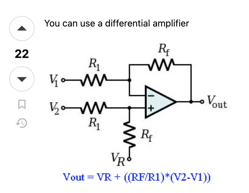
@johnerrington's thread (linked above) has this opamp circuit:
...but it would need a change to move the 0V reference up to 2.5V. Somewhat like this stackexchange circuit:
Per the thread linked above, you need a dual supply to handle the -4V input:

Yes -- What sort of signal is the input signal? How fast does it change?
Hi, @tr1n1ty2435
Welcome to the forum.
Can you please tell us the source of the -4 to +4 signal?
Thanks.. Tom.... ![]()
![]()
![]()
![]()
There is bi-polar input signals; but, the OP-amp is using single power supply; should it not be dual power supply: +12V/-12V?
Thanks, the information helped a lot
it is an ecg signal, which is amplified by the factor 1mv = 1V and it changes fast
thanks, will try this out
And that is...
Do you know how to read a schematic?

Hi,
Have you Googled;
arduino ecg
Tom.... ![]()
![]()
![]()
![]()