Goal
I am trying to create a PCB to charge, protect, boost and measure the voltage of both LiPo and LiFePo4 batterys. All that without leaking much current.
It is supposed to work with a switch so I can select with battery type is used. Howevery, I am running into a problem of the PCB getting too big and bulky and I am wondering which components to choose.
Situation
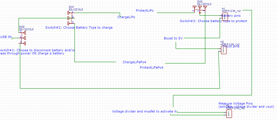
I have alle the charging and protection electronics for both battery types and also one for boosting the battery voltage to 5V to the output pins for powering my arduino. (see cirquit logic attatched)
USB IN should only be passing electricity to the parts for the chosen battery type, which is done by a Switch#2 that can handle 3A.
Problem #1
On the battery pins side, there is also a connection to the protection cirquit that also needs to be switched so the correct protection elements are used. Otherwise the ground of the LiPo would be disconnected by the general low working voltage of the LiFePo4. So I have to use another big switch (#3).
Question
Is there any way I can avoid using another big switch here?
Problem#2
Also, I want an opportunity to turn off the battery completely and just pass through the 5V usb input to the output, which gives me another switch (#1) and brings the problem of current flowing backwards to the boost cirquit when the 5V is passed through form the USB to the 5Voutput pin.
Question
How bad is it, if current is flowing back from the output to the boost cirquit? It would be the part of the boost cirquit that chooses the output voltage of the cirquit. I thought about 3 possible ways to avoid it: Either using another switch (nope!), another diode (disatvantage: voltage drop!) or using a mosfet as shown here:

diode solution:
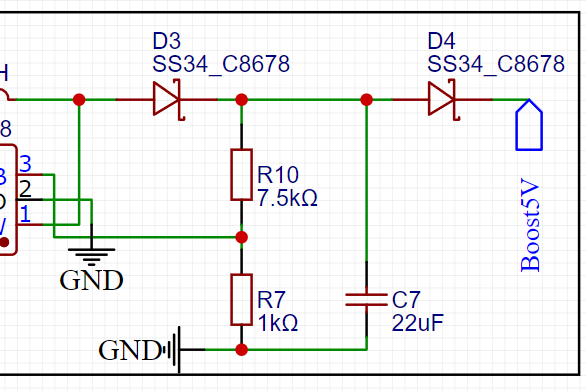
I tend to use the mosfet, which having the gate and source both connected to the boost output, thus would be disconnected when switch #1 is selected for direct output instead of charing the battery?
Problem #3
I want to have it easy to measure the voltage of the battery with my arduino, so I want to use a voltage divider directly on the pcb. However, it would be all the time connected to the battery and leak voltage. So I thought about using another mosfet here that can be activated digitally: If I set an arduino pin high, the voltage divider is activated and measures the voltage.

Question
Is that the optimal way of fullfilling the goal or am I going into the wrong direction here?
Cirquit logic
Actual cirquit
