Charlieplexing Question

I've been working on a binary clock with my arduino, i used charlieplexing but only with 10 leds (4 Arduino pins) well it works but there is a led that is brighter than the others

could someone explain why? thats the only led that is brighter, its assumed to be equal current no?

sorry if my english is bad is my second language

Extra info:
-Resistors are 330 ohms
-Arduino pins 3,4,5,6

if code needed i can post it but i dont think is the code

Sulivan:
if code needed I can post it but I don't think is the code

Why not?

What else would it be?

By the way, that is the wrong way to wire the resistors. The correct way is this:

See also this reference.

#include <Wire.h>
#include <Time.h>
#include <DS1307RTC.h>
tmElements_t tm; 
unsigned int hora=0;
byte Pines [] = {3,4,5,6};
byte matrix1[][2] ={{6,5},{5,6},{4,5},{3,4}};//{-,+} Led
byte matrix2[][2] ={{3,5},{4,6},{5,3},{6,4},{4,3},{5,4}};

// los primeros 4 arreglos son las horas y los 6 ultimos son los min

void Apagado()// Apaga los led o mas bien los pone en alta impedancia poniendolos como INPUTS
{  
  for(int i=0; i<5; i++)
  {
  pinMode(Pines[i],INPUT);  
  }
}

void LedHour(byte k)
{
  Apagado();
  pinMode(matrix1[k][0],OUTPUT); // pone como salida ej: {3,4}, esta en la posicion 0 de la matrix y dentro de esa matrix esta 0 y 1 
  digitalWrite(matrix1[k][0],LOW); //
  pinMode(matrix1[k][1],OUTPUT); // la posicion 0 seria el 3 y la posicion 1 el 4
  digitalWrite(matrix1[k][1],HIGH); //
}
void ledOn(byte n)
{ //Para prender 
  Apagado();
  pinMode(matrix2[n][0],OUTPUT); // pone como salida ej: {3,4}, esta en la posicion 0 de la matrix y dentro de esa matrix esta 0 y 1 
  digitalWrite(matrix2[n][0],LOW);
  pinMode(matrix2[n][1],OUTPUT); // la posicion 0 seria el 3 y la posicion 1 el 4
  digitalWrite(matrix2[n][1],HIGH); //
}


void AmPm(){
  if(tm.Hour > 12){
    hora=tm.Hour-12;
  }
  else if(tm.Hour <=0){
    hora = tm.Hour+12;
  }
  else{
    hora = tm.Hour;
  }
}
  
void setup() {
 Apagado(); // inicializa los leds apagados
  //Serial.begin(9600);

  }

void loop() { 
if(RTC.read(tm)){
  for(int i=0; i<4;i++){ 
  AmPm();
  int x=bitRead(hora,i);
    
  if(x==1){
  LedHour(i);
  }
  else
    Apagado(); 
  } 
  for(int j=0; j<6; j++){
  byte z=bitRead(tm.Minute,j);
  Apagado();
  if(z==1){
    
    ledOn(j);
  }else{
    Apagado();
    }  
}
}
}

a little messy !

thank you! ill re-wire and see how it works

OK, as suspected, your loop() code is asymmetric.

Depending on the time function (and I do not know what status "RTC.read(tm)" actually returns), at the end of the loop you have turned one LED on and it stays on for any period of time until RTC.read(tm) returns TRUE.

It could arguably be suppressed by adding:

void loop() {
  if (RTC.read(tm)) {
    for (int i = 0; i < 4; i++) {
      AmPm();
      int x = bitRead(hora, i);

      if (x == 1) {
        LedHour(i);
      }
      else
        Apagado();
    }
    for (int j = 0; j < 6; j++) {
      byte z = bitRead(tm.Minute, j);
      Apagado();
      if (z == 1) {

        ledOn(j);
      } else {
        Apagado();
      }
    }
  }
  Apagado();
}

But the general "messiness" in the code remains. You need a different approach.

There are two general approaches to Charlieplexing. The poorer one is to light just one LED at a time; this severely constrains the available brightness as for uniformity, you must allocate each LED the same time whether it is lit or not.

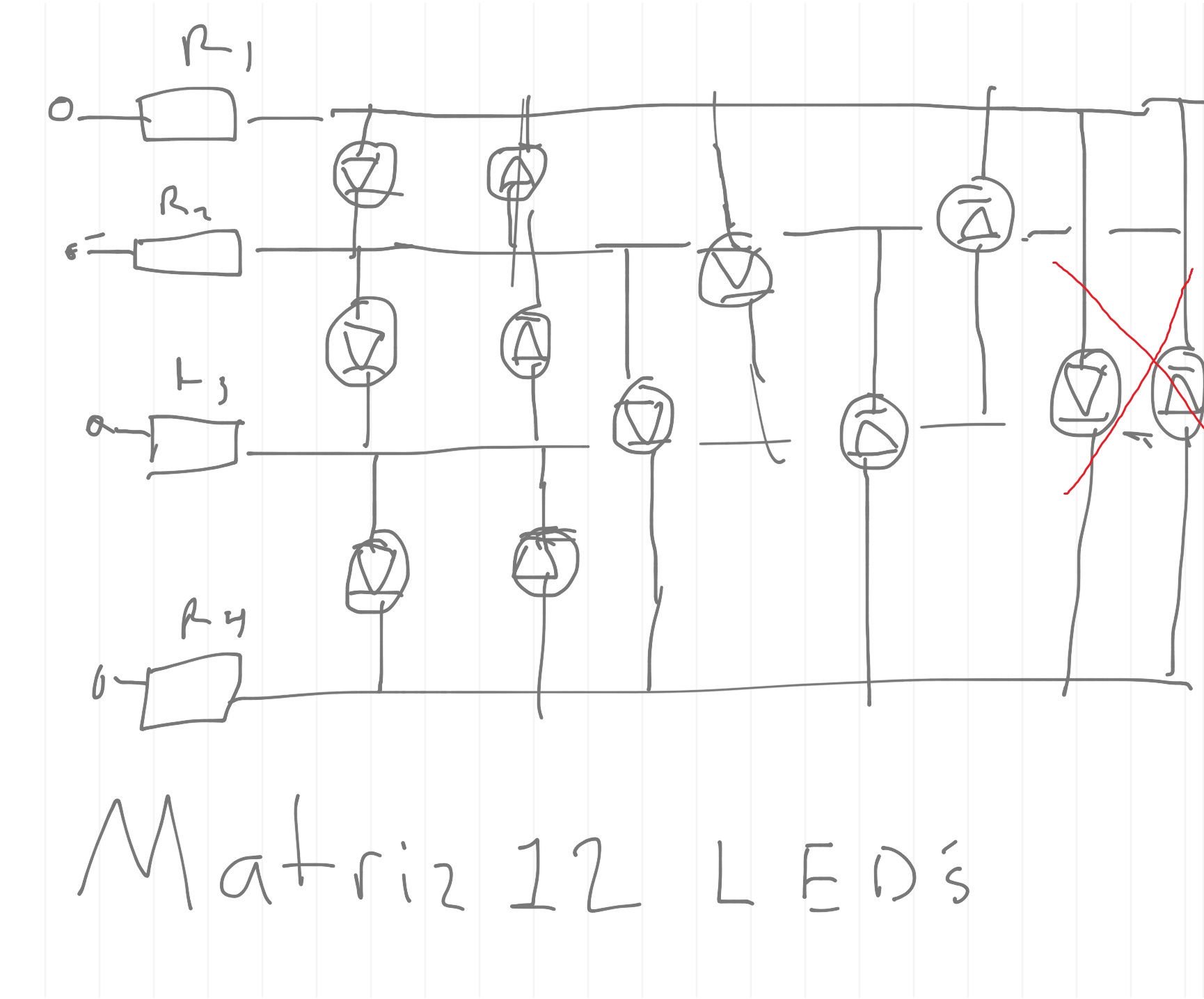
The better approach is to set up a matrix - an array of rows and columns - so that for each selected column, as many rows as need to be, are lit together. You need to be driving the rows only through the resistors as I illustrated and if you really wish to use the maximum driving current, the columns will need emitter follower transistors as in the reference I gave.

In your case, it will suffice that the resistors limit the current to 5 mA per LED so that the common line will draw no more than the rated 20 mA at any one time. The resistor will depend on your LED colour.

Now as to the code, it is also inefficient to light individual LEDs as steps within the Loop(). The correct approach is to use a timer (checking the millis() value) to periodically, as the loop() continues always to repeatedly cycle, step from one column to the next, switching off the outputs for the previous column, setting up the new row data and then switching on the new column.

Alternatively you need not use the timer if the remainder of the loop code is assured to take the same time on every cycle.


Also remember to use Ctrl-T on your code regularly to properly format it so you can see what is going on.

well after re-wiring and using the same code just adjusting some code all the leds are shining equaly , but im thinking about what you said to turn on the leds like a matrix cause im using an unconventional way to turn them on but is the way i figured out the next version ill change the code i just want to finish this version cause is going to be my wearable watch.

thank you for the reference and tips

Sulivan:
if code needed I can post it but I don't think is the code

When someone says "it's not the code" - well, it's the code!

Paul__B:
When someone says "it's not the code" - well, it's the code!

hahaha dam right!