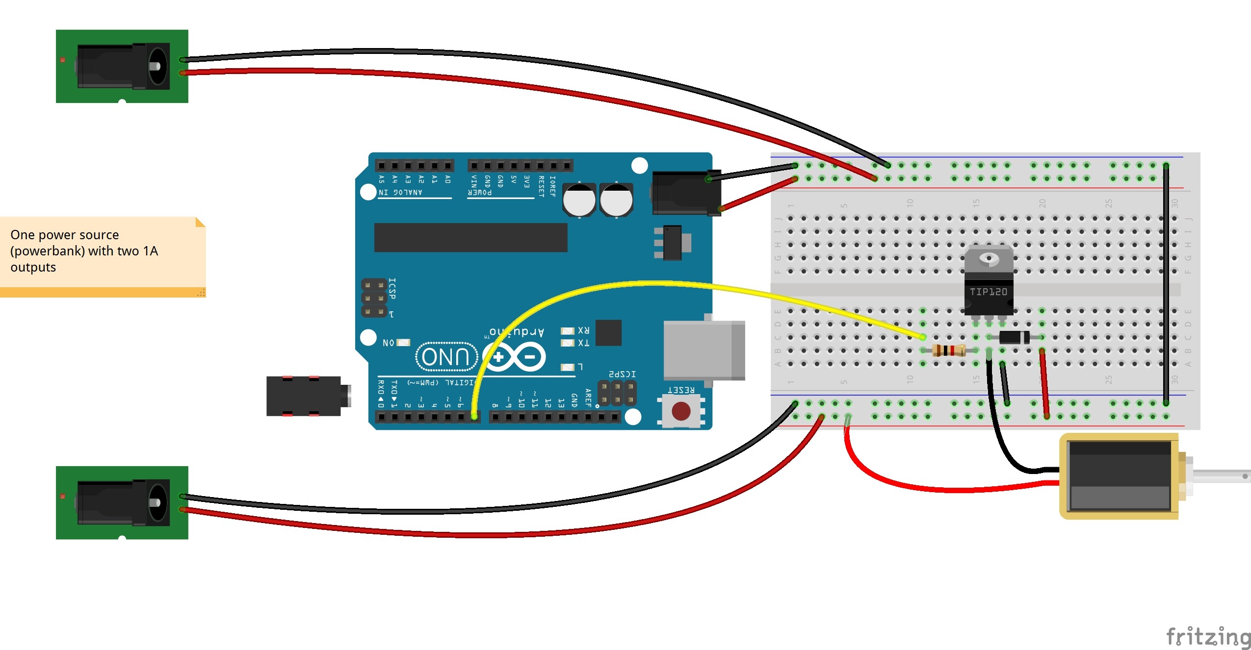
I would like to control a 5volt lock by using Arduino. So I am using a power source that has two outputs of 1 Ampere.
Can I use the power source as I have drawn in the breadboard layout? The purpose is to have one rail for the solenoid and one rail for the Arduino and a sensor that will be added later on.
I am using a power source that has two outputs of 1 Ampère.
Can you clarify this? Do you mean your single power source has 2 independent, unconnected outputs? Or do you mean there are 2 connections to one output, so they are not at all independent.
Are the supplies 5V? I infer from what you have said that they are, but you have not explicitly said so.
If you mean the former then the only thing I can see wrong is you are feeding 5V into the barrel jack on the Uno. If you have a 5V supply you should feed it to the 5V connection and the ground connection.
If you mean the latter then they are not separate so it is futile to wire things to them as if they are.
Thank you for your reply and the remark about the barrel jack.
The powersource is a power bank that I am using that supplies 5volt indeed.
I guess that the outputs of a powerbank are usually dependable so there is no need to connect the grounds?
And maybe you can also answer the question which resistor I have to use between the TIP and the Arduino pin. 1K is common but I cannot figure out how to calculate it.
You are running the motor and the Arduino from the same power source, if the two 5V in the powerbank are connected. That will throw motor noise into the Arduino's digital circuits. Not very good.
Regarding the TIP120 question, if you don't understand transistors, there isn't room in a single (or even multiple) forum posts to explain the choice of resistor value. In reality, it's possible someone made a rough guess just swapped in resistors from the drawer until it worked.
I meant that your calculations for the resistor lead to a circuit that should work.
The TIP120 data sheet that I have claims the DC current gain to be 1000 minimum at Ic = 3A. I would use a higher value base resistor.
I would also avoid using the same supply for the solenoid and the Arduino. With your circuit you will likely observe the Arduino to reset every time the solenoid is activated.
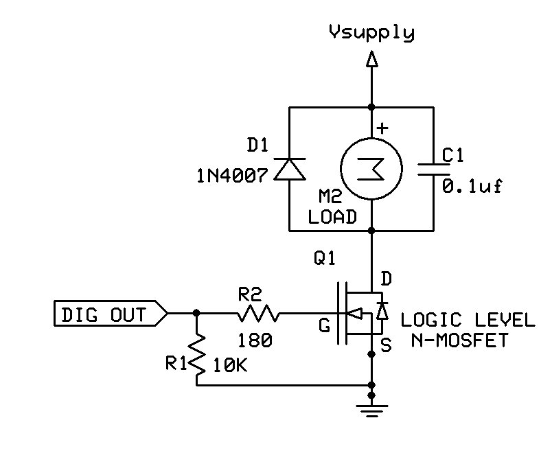
It will work but not optimally. As you can see, there is a lot of power loss due to the high Vcesaturated even with a substantial base drive current. An N Mosfet would be a much better choice.
PerryBebbington:
Can you clarify this? Do you mean your single power source has 2 independent, unconnected outputs? Or do you mean there are 2 connections to one output, so they are not at all independent.
...
If you mean the latter then they are not separate so it is futile to wire things to them as if they are.
On the contrary, it is an extremely good idea!
aarg notes the concern that transients from the motor or solenoid will affect the operation of the logic board. Since very few commercial designs go to the trouble of providing separate supplies for relays and motors, we can conclude that it is just a matter of proper design.
The power supply is supposed to be capable of regulating its output and has an output capacitor as the point of reference. What is important is that the two load circuits are separately connected to this "decoupling" capacitor so that it buffers the transients and there is no common wiring impedance across which to have voltage drops propagate from one part to the other. That is the whole point and concept of "decoupling".
The TIP120 needs to be considered obsolete. Put them away in a drawer as museum pieces. Get some "logic level" FETs.
Paul__B:
On the contrary, it is an extremely good idea!
aarg notes the concern that transients from the motor or solenoid will affect the operation of the logic board. Since very few commercial designs go to the trouble of providing separate supplies for relays and motors, we can conclude that it is just a matter of proper design.
The power supply is supposed to be capable of regulating its output and has an output capacitor as the point of reference. What is important is that the two load circuits are separately connected to this "decoupling" capacitor so that it buffers the transients and there is no common wiring impedance across which to have voltage drops propagate from one part to the other. That is the whole point and concept of "decoupling".
The TIP120 needs to be considered obsolete. Put them away in a drawer as museum pieces. Get some "logic level" FETs.
Well i just finished it on the breadboard. It seems to work just fine. The Arduino Board is not resetting.
However, I am interested in the Mosfet, I just have to replace the TIP120 with a Mosfet and wire it correctly. That is a better way?
MOSFETs are far more energy efficient than the obsolete TIP120. Be sure to use a logic level MOSFET.
I just ordered them so I will change the TIP120. Thank you for your replies. It helps me a lot!!
I do have a followup question concerning the power supply. When the solenoid lock is activated the charging lights on my powerbank are turned on. When I connect a IR sensor to the same power rail nothing happens.
Furthermore if I connect a Robydyn mega mini board with micro usb from from the usb bank the charging lights also turn on. When I connect the Arduino Uno with a usb to the barrel jack this does not happen.
Can anyone explain why the charging lights are turned on and under why?
Paul__B:
The USB does not connect to the barrel jack.
What are you trying to say?
the power bank has two USB outputs. 1 is connected to the Arduino Uno Board and the other to the rail that is connected to the solenoid.
When the solenoid is turned on the charging lights on my power bank are turned on. When the solenoid is turned off the lights are going out. I do not understand why this is happening since the solenoid is not charging the power bank?