I am new to Arduino and have been tinkering a bit.
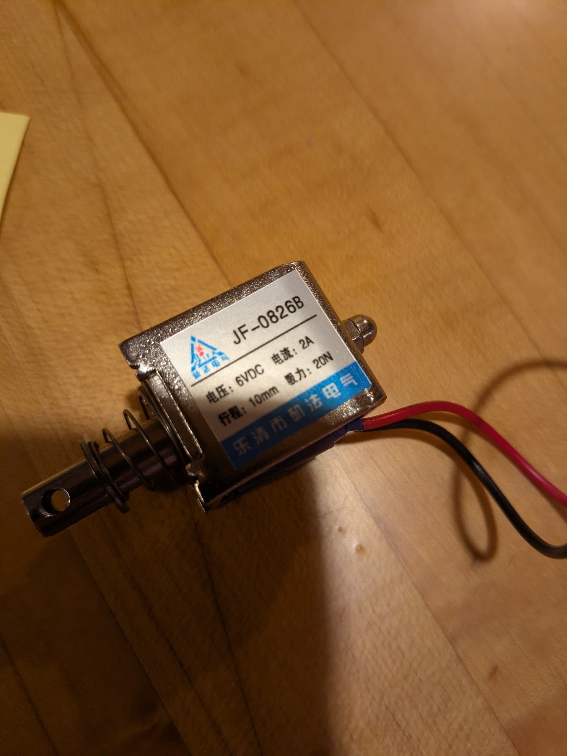
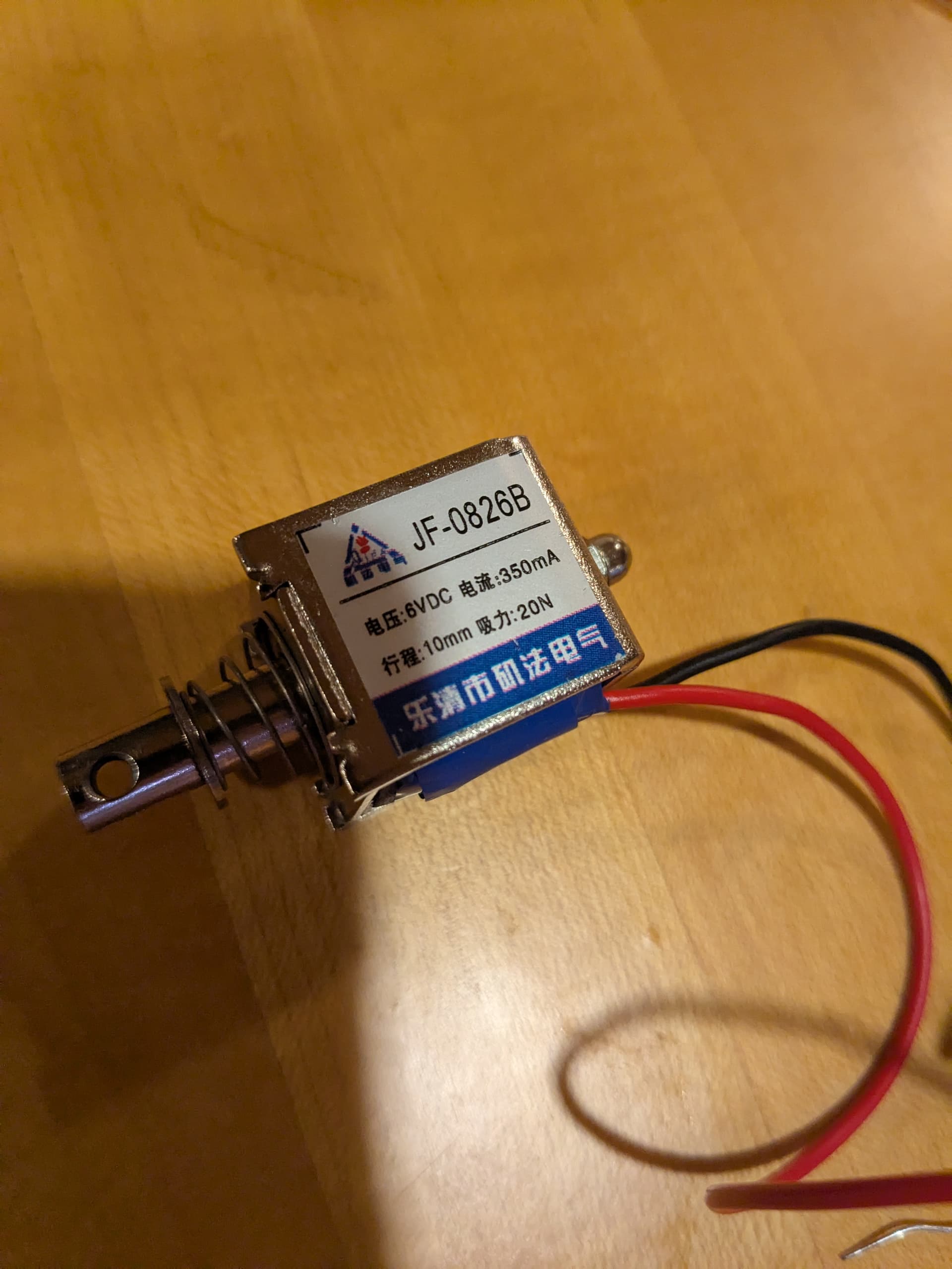
Currently making a circuit to control a small 5/6v solenoid. Specifically this one:
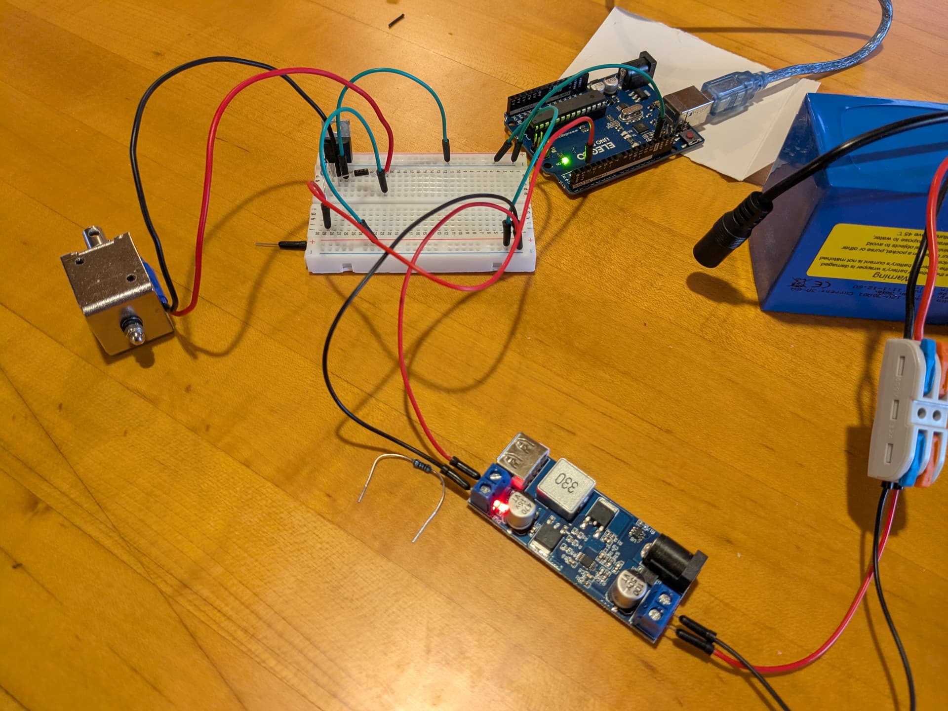
I have wired everything up and coded everything. I feel like the wiring is correct as the solenoid is turning on according to the logic of my Arduino code. The solenoid just seems weak however. I kind of have to help it in order to for it to work.
I'm not sure how to diagnose what is wrong. So I wanted to reach out here for assistance.
Some other specs:
-using a 12v 3amp battery with a buck converter which converts to a little over 5v (5.2 when I checked with multimeter). I have tried powering the Arduino with this battery and with a separate source and saw the same results.
-using an Arduino nano
-using a IRLB8721PBF n channel mosfet transistor
-using a 220 ohm resistor between Arduino pin and the gate pin of transistor
It seems that something else is wrong. Since we cannot see the setup, please post an annotated schematic showing exactly how you have wired it. Be sure to include all connections, power, ground, power sources, and any other relevant details..
Photos are a tad difficult to look at, it's 3d but you can't rotate etc, so it's this flat 2d image after all. Schematics are much better, or if you draw by hand and take a photo of that.
Right, I was lazy It's probably more than the breadboard can handle, and there are several jumperwires, each connection in series with other, adds more resistance.
What you want to do is connect the solenoid so it gets unrestricted power (sounds like Darth Vader..) as little restricted is better wording.
What is the green wire going between the breadboard and the Arduino? Is that GND?
This is confusing to me because typically red would be voltage and black would be GND, but it looks like you may have reversed that convention here. It's just semantics though.
Also, your 220 ohm resistor is letting about 2mA of current in to the gate of the transistor. That should work, but you might consider lowering the value of that resistor to get the transistor to switch states faster and more completely. You should be able to go down to a value as low as 47 ohm with no problem.
The 10K resistor insures it will be off during reset etc.
The link to the solenoid states: "These draw quite a bit of current, 800mA at 5V and 1 Amp at 6V, so you'll want a good strong driver." Ensure that the source of the MOSFET is connected directly to the ground of the converter and that the solenoid's positive terminal is connected to the positive output of the converter.
We can’t accurately assist without knowing the specifics of your setup. Clear, detailed descriptions will allow us to offer the best help possible. Without this information, diagnosing and solving your issues will be much harder.
Give yourself an belated Christmas present and pick up these resources, along with the Arduino Cookbook:
Paper and pencil. Make rectangles for larger items (controller, buck converter, solenoid) and label as to function. Draw straight lines from one component to another where they connect. Label/identify the connection points at each component (power supply positive and negative or D2 for instance).
Make it flow more or less left to right (input to output).
?
The gate of a mosfet has near infinite resistance, so no current flows.
A 100k or higher resistor would still drive the FET without a problem.
The only thing is a fraction longer switching time, which is irrelevant in this case.
The 220 ohm resistor is there to limit Arduino pin current related to the gate capacitance.
Leo..
So i made my circuit with tinkercad which provides a schematice which is nice. Only differences are that tinkercad doesnt give me a solenoid so i just picked a random motor.
Also the batter says 9v. However, I am using a converter to change 12v to 5v. According to the converter specs the ouput from the converter is 5.2v/6A/30W.
Another odd thing is I bought 2 of the same solenoid and one shows as 350 mA and the other 2amps. Its weird because they seem like the same model and I bought them both at the same time from the same place. Also, the ada fruit link I shared claims they should also work at 5amp. So i am not sure what to think haha.