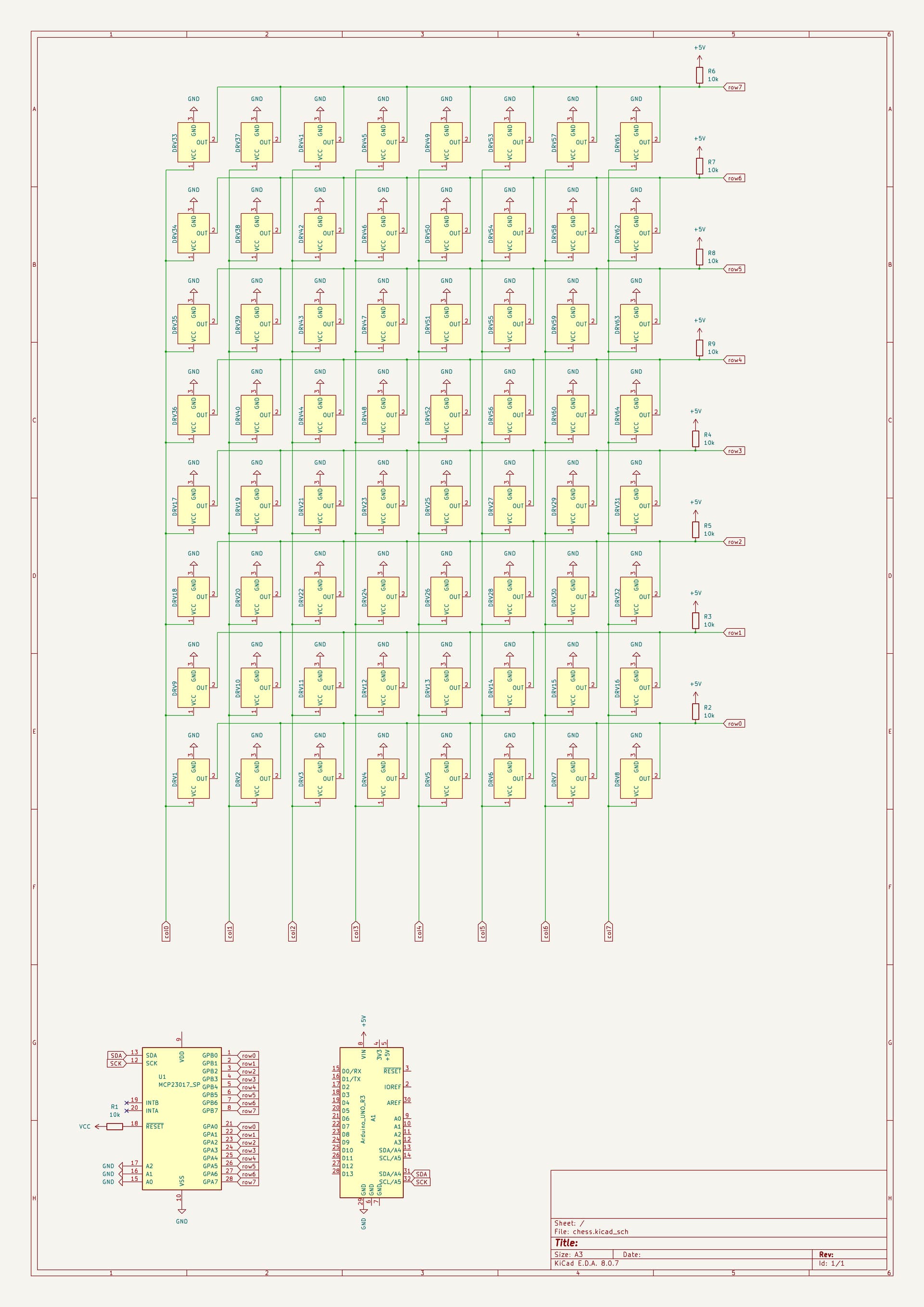
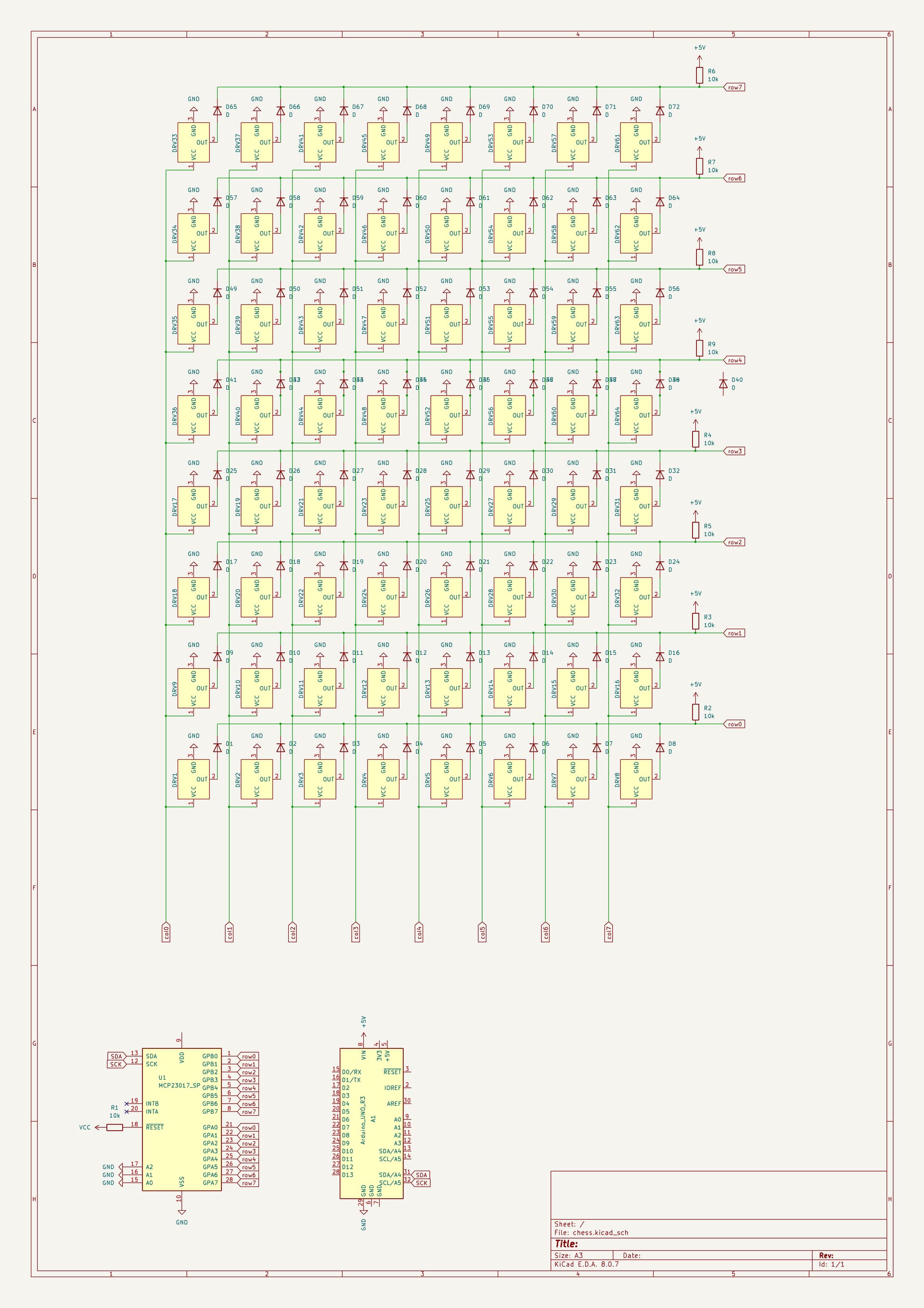
I am planning to make a digital chess board. The chess pieces will have magnets in the bottom of them that the hall effect sensors should hopefully pickup. The sensors that I am planning to use are DRV5032A hall effect sensors. I have made a schematic in kicad. I am making this post to make sure that I haven't made any silly mistakes
Look at the data sheet. See the decoupling capacitor on every driver? Where are yours?
I doubt you can make a matrix with these, but try with two first. A lot depends on what sort of scanning algorithm you will use to drive the matrix.
What sort of package are you using? I would advise using the flat pack.
What sort of size will this be? The sensors might respond to adjacent magnets if it is too small.
Also how do you plan to change the sample rate of the sensors?
This link might help you, but it is all in German, so an auto translate program might be helpfull:- Computer Chess (in German)
Yes it will play chess with me, I will have a raspberry pi 4 running stockfish and python-chess communicating to the ardunio over serial. The lights will be WS2812B leds. Also I will put decoupling caps everywhere
While I do like a bad pun, I can't say I have much respect for "Nuts and Volts" It seems very amateurish, and has very dogie theory and speculation in their work. Not as bad as "instructables" but not a lot better.
So having read the decoupling tutorial, be if you can spot what was wrong with the decoupling on the LEDs.
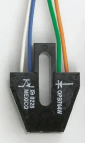
I think a better results would be got using the IR diode in a reflective optical sensor like this.
It shows you the range of sample frequencies for all the types of sensor.
Also Page 1 says:-
By incorporating an internal oscillator, the device samples the magnetic field and updates the output at a rate of 80Hz, 20Hz or 5Hz for the lowest current consumption.
So what makes you think they are not variable?
The data sheet says:-
Omnipolar and unipolar magnetic responses are available.
Do you know the difference between these two modes?
What version of the sensor are you thinking of buying?