I am new in electronics. I have some arduinos at home and I have done many projects with them. Now I want to make my own PCB board for specific task - small robot with 2 motors, sensors, gps etc. It will run on battery so I want to make it very power effecient therefore I don't want to solder whole arduino on my PCB, just required components.
And this is where I need help with choosing right MCU IC for my PCB.
I need more digital and pwm pins as ATmega328p.
It should run stable on 3.3V (most of my sensors require this voltage, not 5V logic)
It should have more memory for sketch as ATmega328p does
It should be programmable with Arduino IDE (because coding there is fast and easy)
USB-compatible can be advantage because I will not need to use some USB-UART converter
I saw some projects with ATmega2560 running on 3.3v but it was unstable and that MCU is not designed for 3.3V - I don't want to use these.
Arduino Due's ATSAM3X8E seems to be suitable but it has more pins than I need and is more power hungry because of it's speed.
You will help me if you can suggest me some MCU IC for my requirements or suggest me some finder-tool to find suitable IC.
There are versions of the ATmega2560 that are specified to run at 3.3V/8Mhz.
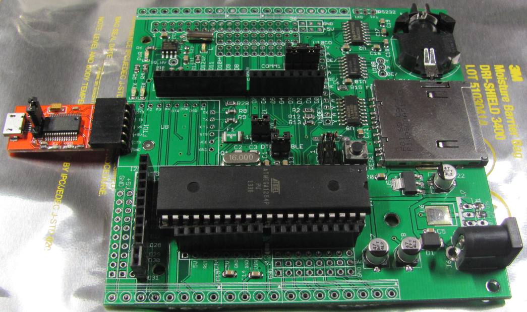
Then there is the ATmega1284P, 4 times the flash, 8 times the memory and 8 more I\O pins over ATmega328P. The TQFP44 version is easier to solder than the TQFP100 of the mega2560, and the 40pin DIP version is dead easy to solder.
If your going for battery power, its best to leave the USB-Serial convertor off, an ATmega1284P will then have a deep sleep current under 1uA.
The Atmega2860V will run at 3.3V. Still can be difficult to hand assemble those on a board. Metal stencil for appling solder paste comes in handy.
I do a lot of projects based around the '1284P, both SMD & DIP. 32 IO is plenty for most projects. And sometimes it's less expensive to have a shift register or two or some other chip with the 1284P ($5.40) vs having the 2560 ($11.85) do everything.
(current 1-lot price at Digikey.com for SMD parts)
Put on header pins for an FTDI Basic or equivalent, plug one on to download/debug code, remove it when done. Also frees up the processor to do other stuff vs managing the USB interface.
Thanks Robin2, srnet and CrossRoads for fast replies and good advice.
ATmega1284P looks good. I will try it with this.
I want to have USB-Serial converter on-board (I hope FT232RL in 3.3V mode will work) because of quicker sketch uploading and debugging. If I am right, this will not need much power when in idle mode (<1mA).
I hope 8MHz doesn't change much with uploading and running sketches (e.g. delay() issues which I found somewhere on other forums).
astetyne:
I hope 8MHz doesn't change much with uploading and running sketches (e.g. delay() issues which I found somewhere on other forums).
As long as you specify the correct clock frequency when burning the bootloader and programming the chip in the IDE there should not be any problem with uploading, delay(), etc. You will need to adjust your code if you are doing anything that directly depends on clock frequency (such as direct manipulation of timers, etc) that is not handled by the compiler.
What can get you into trouble is changing the crystal frequency without making the appropriate changes in the bootloader or the IDE. You can't simply pull the crystal off a 16MHz board and replace it with 8MHz.
astetyne:
I want to have USB-Serial converter on-board (I hope FT232RL in 3.3V mode will work) because of quicker sketch uploading and debugging. If I am right, this will not need much power when in idle mode (<1mA).
It makes no difference to speed whether the Serial uploader is on board or off.
I have always just fitted a 5 pin header for programming when using bare bones Atmega328p, ATmega1284p and Atmega2560, just like on a Pro Mini, the serial uploader is then external and removeable.
1mA idle current is absolute masses of wasted power for a battery project. A set of AAs would only last 116 days if this was the lowest current.
Leave of the serial upload circuit and the same AAs could last 127 years ........... so 1mA is a lot.
srnet:
It makes no difference to speed whether the Serial uploader is on board or off.
I meant speed of development - insert one USB cable from laptop to PCB, no matter where I am. (I am thinking about USB-C support for my PCB)
You are absolutely right with that 1mA but this can be fine for me because there will be also neo-7m chip and IMU chip. (I know, these are not very power effecient but I need them, so additional 1mA is fine).
david_2018:
You can't simply pull the crystal off a 16MHz board and replace it with 8MHz.
Should I use external oscillator for 8MHz? Or is internal 8MHz oscillator fine?
Should I use external oscillator for 8MHz? Or is internal 8MHz oscillator fine?
Either should be ok, the internal oscillator is not nearly as accurate as a crystal or resonator, but you are using a GPS module so have access to an accurate clock reference if needed. The main thing is that you specify the proper frequency when burning the bootloader and compiling the code. Burn a 16MHz bootloader onto a chip that runs at 8MHz, and all the oscillator-based timing will be running half as fast as expected.
I dont understand the supposed problem myself. None of the 'development boards' I work with have built in USB support.
I would admit that at the start of a days development work it might sometimes take me an extra second or two to plug in the USB to Serial adapter then have to plug that into the 5pin program header on the development board.