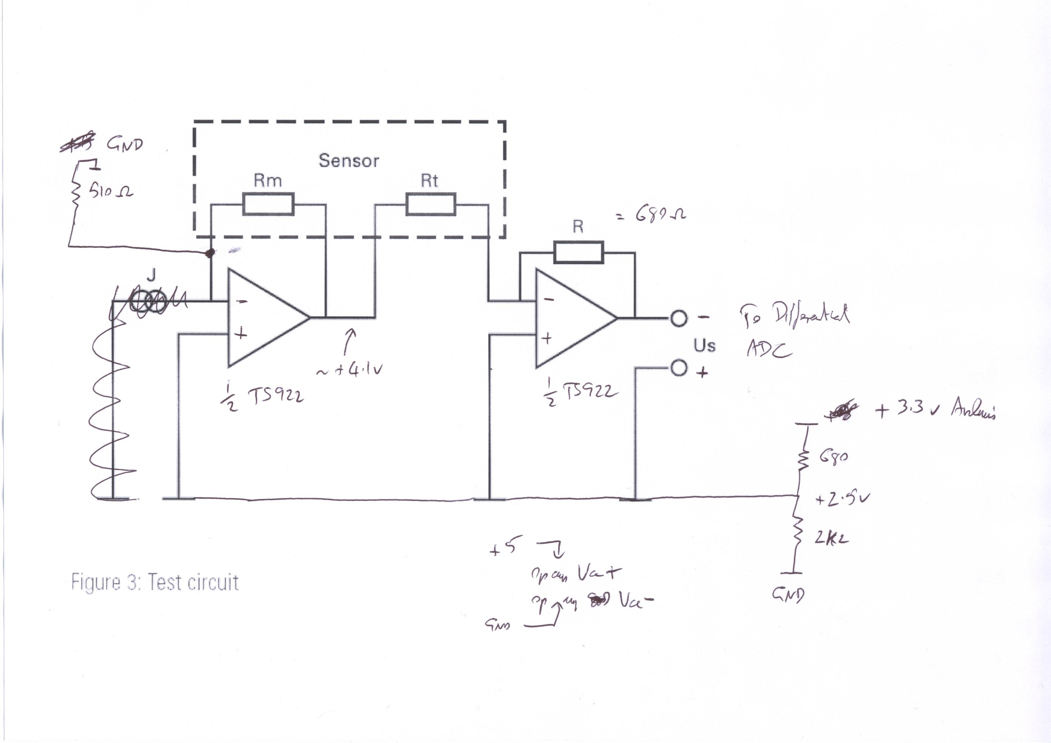
A test circuit is shown as figure 3. But it is to sketchy for me to understand. All I see is some kind of op-amp. I can not recognise it as a Wheatstone bridge either. And the “J” with two rings, I have no idea what that means.
I am planning to read the data with a MCP3422, a very sensitive 18bit ADC. so maybe amplification wont be necessary?
Actually I hope to use either MTCS2200 or MTCS2600. But their datasheets have even less information.
Preferably, you should use the circuit on the data sheet, adapted to use single-rail op-amps and a single +5v supply. However, the following scheme drives the sensor under similar conditions and may work for you:
connect sensor Common to GND
connect sensor Rm to an Arduino analog input pin and through a 680 ohm resistor to +5v
connect sensor Rt to a different Arduino analog input pin and through a 1.2k resistor to +5v (adjust the 1.2K higher or lower if necessary until the readings from the 2 pins are about the same in pure air)
then the ratio of the readings from the 2 pins will be about 1:1 in pure air but will vary with methane concentration.
As temperature varies, the readings from both pins will vary; but at a constant temperature the reading from the pin connected to Rm will decrease with increasing methane concentration (at 100% methane it would be about 93.5% of the value it is in pure air, if I have understood the data sheet correctly).
The resolution of the ADC is likely to be the limiting factor in the resolution you can obtain with this setup. [EDIT: just noticed you are proposing to use an 18-bit ADC, so ignore that.]
Here's an adaptation of the test circuit in the data sheet. I've specified a rail-to-rail output op-amp on the assumption that you only have a +5v supply available.
Glad you got it working. You may have a problem using the TLC272 op-amp in that circuit, because with a 5v supply the high level output voltage of that chip is only guaranteed to go up to 3v, and the circuit calls for up to 4.1v.