Circuit Schematic Question

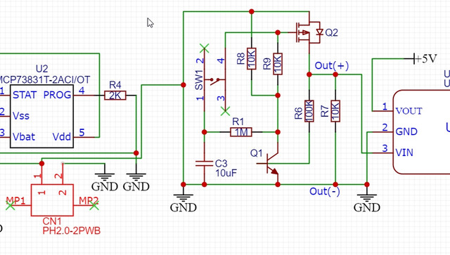
I could really use some help/guidance on a couple of issues I'm having. The first issue is that I'm trying to incorporate a soft latching power switch into my project. I'm trying to use the same circuit as the photo below.

The circuit is from here

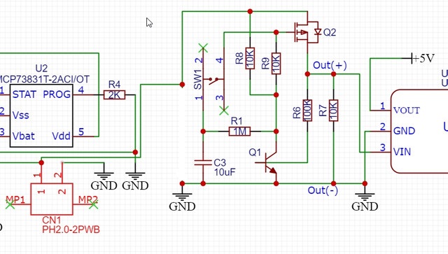
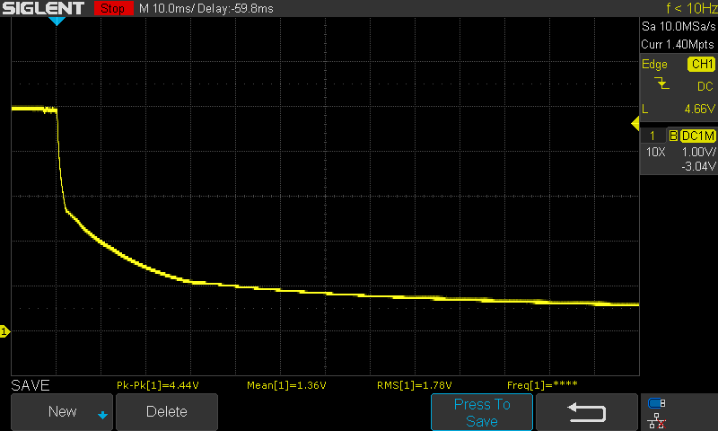
Below is an image of my current schematic. It may be a noob question but I'm completely unsure about how I'm suppose to connect the positive terminal of the JST battery connector to the soft latch circuit. The idea is that the battery would be enough to trigger the circuit and then that would run to the U3V12F9 boost converter which would then go to on to power the rest of the circuit with 5V. I'm not sure if I'm connecting the positive and negative outputs of the circuit to the converter correctly either. :confused:

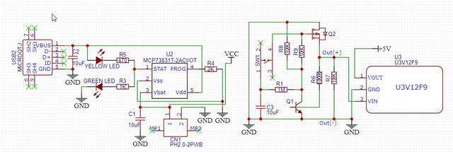
My other issue is how to choose the correct BJT for Q1. For Q2 I've chosen a P channel MOSFET, the datasheet says that it has gate operator with voltages as low as 1.8V so I believe this should work. I've been researching about BJT's but I don't seem to be getting it. I'm still very new to electronics so there is a lot I don't know that others would probably consider common sense. Can anyone offer a suggestion or at least fill me in on what I should be looking for when selecting a component for Q1? I forgot to mention that the max draw of the system is 1 Amp but its usually much less. Also if there are any other glaring mistakes on my schematic please let me know, any help is greatly appreciated!

Battery goes in place of the DC supply symbol in the first circuit.

You have connected the load correctly.

You haven't said what the battery voltage is.

The p-channel MOSFET you've chosen has a gate-source absolute maximum rating of +/-8V
which is very low, but I presume the battery voltage is less than 5V given the boost converter
so that is probably fine.

Q1 is literally any small-signal general-purpose NPN device - they all behave the same to a
first approximation.

The soft-switch circuit only triggers when the button is pressed, and latches until power is removed.
Is that what you intend?

Thank you for taking the time to help.

MarkT:
Battery goes in place of the DC supply symbol in the first circuit.

Connecting the battery in place of the DC symbol is the bit that's confusing me. I've highlighted the battery JST connector in red in the photo below. Can I simply take the positive terminal and connect it straight to the circuit like in the photo? I'm assuming that the negative terminal can go to the common ground but I'm not absolutely certain.

MarkT:
You haven't said what the battery voltage is.

The battery is a single cell lipo and the voltage is anywhere from 3.7-4.2 volts.

MarkT:
The p-channel MOSFET you've chosen has a gate-source absolute maximum rating of +/-8V
which is very low, but I presume the battery voltage is less than 5V given the boost converter
so that is probably fine.

Yes that's correct, it's a 5V system so it'll never get above that.

MarkT:
Q1 is literally any small-signal general-purpose NPN device - they all behave the same to a
first approximation.

Wow I didn't realize that they were so forgiving, I figured if I selected the wrong BJT then it would cause the circuit to fail. I'm going to go with this one then. I'm assuming this will be fine?

MarkT:
The soft-switch circuit only triggers when the button is pressed, and latches until power is removed.
Is that what you intend?

My understanding was that the circuit would turn the power on from the first press and off with the second.

"The circuit in Figure 1(a) is configured to latch power to a low-side (ground-referred) load. It works in ‘toggle’ mode; that is, the first switch closure applies power to the load, the second removes power, and so on....
When the switch is momentarily closed for a second time, the voltage on C1 (by now approximately equal to +VS ) is transferred to Q2’s gate. Since Q2’s gate-source voltage is now roughly zero, the MOSFET turns off and the load voltage falls to zero. Q1’s base-emitter voltage also falls to zero and the transistor turns off. Therefore, when the switch is released, there is nothing to hold Q2 on, and the circuit reverts to its ‘unlatched’ state, where both transistors are off, the load is de-energized, and C1 discharges via R2."

That is taken directly from the site that I found the circuit from. So you're saying the circuit won't power off on the second press? :confused: That is definitely not desired. I just want the system to turn on with a press, and off with the second.

No, the circuit latches permanently once the button is pressed. If you want a toggling power switch its no use.

Perhaps adapt something like this to drive the pFET:

Kuusou:
Wow I didn't realize that they were so forgiving, I figured if I selected the wrong BJT then it would cause the circuit to fail.

In this case - switching a very small current - just about any will do. My go-to small signal NPN is the BC547, another common one is the 2N2222, but there are many more.

The first page of the list in that link shows transistors with SOT-23 footprints, are you sure you want that?

I just want the system to turn on with a press, and off with the second.

Push on-push off switches are available.

It's possible to make the OP's circuit work, but many of the values must be changed and it will not be very responsive. It would need about 5 sec or more between cycles for the RC time constants.

I think the circuit does push-on, push-off. It seems the description from the original site describes how it works, and I assume it was tested before it was piublished.

But your connection from the battery to this circuit is wrong. You are grounding the battery positive. See the attached revision instead.

One other potential issue. If you power the load while you are charging the battery (USB is connected), the load current is supplied by the charger. That may confuse the charger, which wants to terminate charging when charging current falls below 10% of full charging current. If the load current is too much, that 10% will never happen, and you could overcharge the battery, with explosive results. You might look at the MCP73871 instead, which has a "load sharing" component that takes care of that problem.

If your load is a microprocessor, a simpler circuit would let you control the NPN transistor from a GPIO port of the processor, so your software could shut itself off. The push button then not only turns on the power initially, but also serves as an input signal to the processor. I'll attach an example circuit.

circuit-design3.jpg

I agree the circuit will turn off at the second button press. But why do you think the battery should explode? The charger should not let more than 4.2V to the battery and so it will be fully charged and won't charge more. I don't see any overcharge risk.

Smajdalf:
I agree the circuit will turn off at the second button press. But why do you think the battery should explode? The charger should not let more than 4.2V to the battery and so it will be fully charged and won't charge more. I don't see any overcharge risk.

It will charge more. If you leave 4.2V on a lithium rechargeable , it will continue to take on charge, and will eventually swell up and possibly catch fire or explode. ALL lithium chargers are designed to completely terminate charging, and the termination point is typically when the charging current has dropped to 10% of the full charging current. They never ever "trickle charge" a fully-charged lithium battery.

As a hobbyist, I try to remember that there are two general areas which can end up really hurting you, or worse. The first is anything to do with mains. The second is mishandling lithium batteries. They are dangerous. If your charger is supplying current to your load as well as charging the battery, and the load current exceeds the 10% value, you are flirting with disaster. This is solved by including a "load sharing" circuit:

Smajdalf:
I agree the circuit will turn off at the second button press. But why do you think the battery should explode? The charger should not let more than 4.2V to the battery and so it will be fully charged and won't charge more. I don't see any overcharge risk.

You are overlooking the 47uF decoupling capacitors on the Arduino load which can prevent the NPN
switching off unless the time constants are adjusted - also voltage rails for digital circuits often don't drop
very far immediately, as as soon as the oscillator stops the current consumption of a CMOS circuit drops
to near zero.
Here's an Arduino Mega (well Seeeduino Mega in fact) 5V rail when its unplugged from USB, at 10ms
per division:

It takes 2ms before the osc. stops, then the decay slows down considerably, taking 10ms to drop to 2V and
30ms to drop to 1V. At this point the NPN transistor would likely still be on when you release the button... This board has 22uF and 10uF caps in fact, not 47uF like the Uno, so it would be worse.

Its fine for switching resistive loads, but its not general and its not the simplest approach either which is to
use a DQ flip-flop which is designed to toggle reliably and not depend on the load's properties.

To fix the circuit you probably want to set the discharge time constant to 0.3s or so, and the capacitor
recharge to 2s or so.

There must be a chip out there that does all this, debouncing a button, integral high-side MOSFET and toggling
logic, didn't find one when I searched though.

@MarkT: The Arduino filtering caps will be hidden behind the step up converter. It should introduce at least one diode drop or block them completely. But you are right - the circuit is tricky and there are simpler and more reliable ways.

@ShermanP: Does the linked app note say keeping the batteries @4.2V makes them explode? They say

It is not recommended to continue to trickle charge Lithium-Ion batteries.

But AFAIK "trickle charging" is used in NiMH batteries an mean "very low continuous current regardless of voltage". Which would kill a Lithium battery.
It is true many charge controllers use charge termination at 10% of set current. I have never thought about it. I guess it is to reduce stress of the battery and prolong its life?
The linked app-note also says

The MCP73811/2 Li-Ion battery charge management controllers with no auto-termination may be a viable solution for the type of applications that are designed to simply connect the system load to the LiIon battery.

It is strange. They are afraid the extra load may disable auto-termination and suggest using a charge controller without auto-termination as a remedy. Why? I looked into the datasheet of the mentioned MCP73811/2 and it simply says no auto-termination is provided. It does not warn it can cause any damage to the cell or say it is needed to provide an external termination method.
Do you know a source saying a Lithium battery may explode when connected to 4.2V for prolonged periods? From this it looks like it "only" degrades its performance.

I don't understand what you're saying about the MCP73871. Charge termination is described in Section 4.7 of the datasheet.

Here's an article about lithium charging:

Included there is this statement:

"Li-ion cannot absorb overcharge. When fully charged, the charge current must be cut off. A continuous trickle charge would cause plating of metallic lithium and compromise safety."

Also see the "trickle charging" entry on Wikipedia.

MCP73871 has charge termination. MCP73811/2 does not.

Wiki says

Trickle charging means charging a fully charged battery at a rate equal to its self-discharge rate...

however the references 6 says a trickle or maintenance charge is

A relatively small trickle or maintenance charge rate of 0.03C to 0.05C is applied to the battery to compensate for self-discharge.

The reference 5 probably uses similar definition but only the second half of the paragraph is available.

It is clear trickle charge defined as constant current might blow a lithium battery. IMHO the Wiki's definition is wrong and should be updated.

Also the battery university says

Prolonged charging above 4.30V on a Li-ion designed for 4.20V/cell will plate metallic lithium on the anode. The cathode material becomes an oxidizing agent, loses stability and produces carbon dioxide (CO2). The cell pressure rises and if the charge is allowed to continue, the current interrupt device (CID) responsible for cell safety disconnects at 1,000–1,380kPa (145–200psi). Should the pressure rise further, the safety membrane on some Li-ion bursts open at about 3,450kPa (500psi) and the cell might eventually vent with flame.

This could happen with CC charging but should never happen with CV - the battery voltage should never exceed 4.20V and so it should not vent.
Do you have a source that clearly states a prolonged connection of a lithium battery to 4.2V may cause it to burst?

I wouldn’t trust the 4.2v voltage reference

Smajdalf:
Do you have a source that clearly states a prolonged connection of a lithium battery to 4.2V may cause it to burst?

Not at hand. Everything I've read about the design of lithium chargers says they must terminate charging when fully charged, and a cell is never left with 4.2V applied. Somewhere along the line I've read an explanation of why that's necessary for lithiums, but can't remember where I saw it. But basically the idea was that at 4.2V the cell will continue to take on charge. Of course you are welcome to disagree. And if you find a reference that says all the lithium chargers which terminate charging don't really need to do that, I'd like to see it.