I'm trying to create a circuit that will be able to act as either the sending or receiving end of a camera shutter release (intervalometer). In particular, it will include a 2.5mm aux jack for use with the Canon shutter release system described here. To trigger the camera shutter, the sleeve (ground) and tip (shutter signal) should be connected.
To trigger the shutter with my microcontroller (ESP8266), I've used an optocoupler to connect shutter and ground while retaining isolation between devices. However, I also want to be able to plug in a remote shutter release, which is essentially just a switch, and detect its state as well using the same 2.5mm jack.
I'm still pretty new to electronics, but I understand that to detect the state of the switch I can just pull a GPIO pin up/down on one side and connect GND/VCC on the other side. My question is whether it's possible to safely do so while still being able to retain shutter release (switching) functionality when a camera is plugged in.
My fear is that no matter how I do it, I risk feeding too much voltage into either the camera or microcontroller. I have no guarantee of the camera's voltage, which is why I opted for an optocoupler for the original shutter release circuit. A side question is whether having common ground would be preferable (considering the camera will probably be battery-powered), and if so maybe this can be done with transistors? If the ground is shared, the camera can be triggered by bringing connecting the shutter pin the ground (digitalWrite(LOW)).
I would be using this 2.5mm jack, which has pads for sleeve (ground), ring (audio right/focus), tip (audio left/shutter), and tip switch.
I can't read and keep track so I am confused. You know that saying a picture is worth a thousand words - in engineering that estimate may actually be low.
Draw a block diagram of all the individual parts of this, showing who can talk to whom, with attention to whether this is simultaneously or is a collection of devices that is to be used in multiple deployment scenarios.
If it is to be used differently at various times, draw a block diagram of each way the three or however many whatevers you are talking about are connected.
Pencil on paper and you cellphone work well for this.
OK, I am guessing… you want to be able to either take a picture by pressing a button OR by automatic control via some sketch you have in mind.
Like say the Arduino could be taking a picture every five minutes, but you'd like to press a button whenever to tak an additional picture.
If that's right, say. If it's wrong, say how.
If I have guessed correctly, is there any objection to simply using a pushbutton that the Arduino could keep track of, and then use the same interface to the camera as the automatic process uses?
Looking at your diagram, I see nothing that feeds any voltage to the camera. In fact, it looks like a pushbutton placed across the opto out at 4-5 would work.
You have four different blocks and a note that says "should be able to work in either scenario"… to what does that refer? What should be able to work in either scenario?
Don't worry about me, just now I've had too much of one thing and not enough of another, I should just sit on my thumbs and watch.
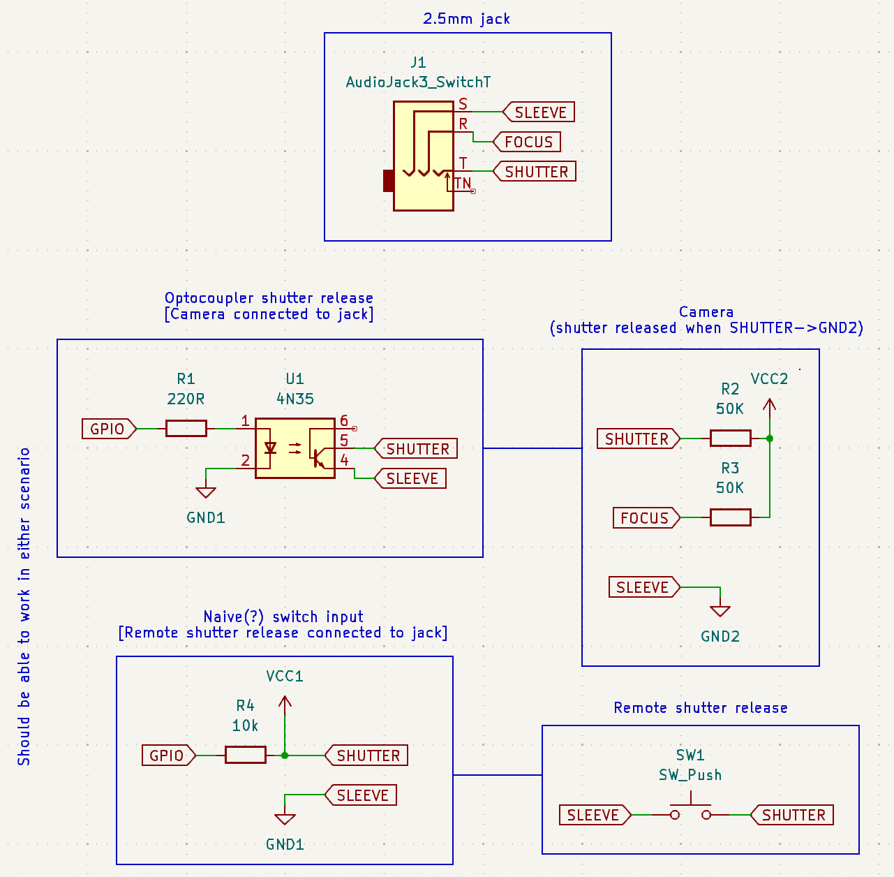
No problem, it's definitely my fault for not explaining clearer. There is a 2.5mm audio jack, which will be on a PCB with an ESP8266. There are two modes of operation I have in mind:
Camera connected to jack. In this case, the EPS8266 should be able to trigger the shutter, hence the optocoupler idea.
Remote shutter release connected to jack. This is an external device (like this) that is meant to plug into the camera directly, and is essentially just a fancy switch (but can be more sophisticated). However, I want to be able to plug it into the jack and keep track of its state.
So, either the camera or the remote shutter release could be connected to the jack at any given time. Use cases for the former would be what you mentioned: time-lapse or something similar. Use case for the latter would be, for example, triggering the camera shutter over WiFi (using ESP8266) whenever the remote shutter release is pressed (since many cameras don't have the physical shutter release port anymore).
I can't quite figure out how to support both of these modes using one jack. If it helps, there's also the tip switch (TN on the top diagram), which is closed whenever something is plugged in. Thanks again!
If the camera is connected, the Arduino can control the shutter. Writing HIGH to the pin will be the same as pressing the button. Take a picture.
If the remote shutter device is instead connected, the Arduino can read the state of that switch or switch equivalent. A LOW reading would correspond to a closed switch. Do the Wi-Fi thing for the camera.
@Paul_KD7HB reminds us to check the voltage and polarity. Any remote shutter device that is not just a mechanical switch must be able to pull down the 4K7 resistor, which could be much larger if need be.
To act as a switch, an output circuit like your opto is required.
To detect switch state, an input circuit is required.
Is there a reason to require both of those circuits to the same 2.5mm jack? The circuits and sketch will be complicated to make this work. An easier option would be an input jack and an output jack. Both jacks could be active simultaneously with much simpler firmware.
For the input jack circuit, I would consider using another optocoupler to isolate the jack from the ESP pins.
This makes sense to me, except it's assuming that both pull-up voltages will be the same (e.g. 3.3V), right? Would there be issues in the case that the camera (SHUTTER) pull-up voltage is higher? I'll probably play around with this on the breadboard to see if I can understand it better
I agree, I guess I just wanted to explore the viability of this idea before committing to adding another component.
Since the shutter release is basically a switch, would you still need to connect to the ESP GND/VCC in order to drive the optocoupler for an input jack?
Why so? AFAIK the OP wants to trigger the camera if
A: the opto triggers the shutter
OR
b: an external switch triggers the shutter.
So it needs:
a transisitor or opto - isolator to act as a switch driven by an output pin; and
a suitably protected connection (eg via a 10k resistor) to a pin assigned as an input, to detect the trigger state.
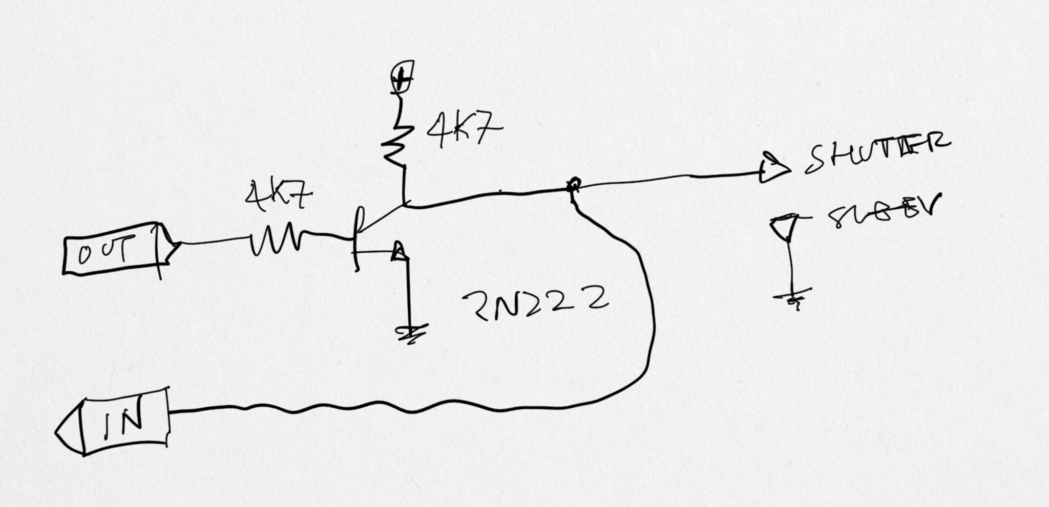
I'm still not sure I understand what's needed here, but here's a circuit that uses two diodes. The push button grounds whatever is on the left (it would be the camera trigger line in this case), and at the same time serves as an input to the MCU. The diodes prevent either side from interfering with the other, and allows high voltage to be switched safely.
Yes, that looks right. I apologize for the lack of clarity; as this is my first time asking about something like this, I'm still leaning a lot about how to communicate these concepts. Thank you for drawing the diagram that I probably should have included from the start!