Hi all,
I am uploading the following code to a STM32F103C8 but it is not working properly. Part of the code runs fine but then it stops and becomes still.
#include<Wire.h>                   //Include Wire library for using I2C functions

#include<SoftWire.h>

#include <LiquidCrystal.h>         //Include LCD library for using LCD display functions


#define MCP4725 0x60            //MCP4725 address as 0x60 Change yours accordingly


const int rs = PB11, en = PB10, d4 = PB0, d5 = PB1, d6 = PC13, d7 = PC14;

LiquidCrystal lcd(rs, en, d4, d5, d6, d7);


unsigned int adc;

byte buffer[3];


void setup()

{

  Wire.begin();                    //Begins the I2C communication

  lcd.begin(16,2);                 //Sets LCD in 16X2 Mode

  lcd.print("CIRCUIT DIGEST");

  delay(1000);

  lcd.clear();

  lcd.setCursor(0,0);

  lcd.print("STM32F103C8");

  lcd.setCursor(0,1);

  lcd.print("DAC with MCP4725");

  delay(2000);

  lcd.clear();

}


void loop()


{

  buffer[0] = 0b01000000;            //Sets the buffer0 with control byte (010-Sets in Write mode)

  adc = analogRead(PA0);             //Read Analog value from pin PA0


  float ipvolt = (3.3/4096.0)* adc;  //Finding voltage formula

  buffer[1] = adc >> 4;              //Puts the most significant bit values

  buffer[2] = adc << 4;              //Puts the Least significant bit values


  unsigned int analogread = analogRead(PA1) ; //Reads analog value from PA1


  float opvolt = (3.3/4096.0)* analogread; //Finding Voltage Formula


  Wire.beginTransmission(MCP4725);         //Joins I2C bus with MCP4725 with 0x60 address


  Wire.write(buffer[0]);            //Sends the control byte to I2C

  Wire.write(buffer[1]);            //Sends the MSB to I2C

  Wire.write(buffer[2]);            //Sends the LSB to I2C


  Wire.endTransmission();           //Ends the transmission


  lcd.setCursor(0,0);

  lcd.print("A IP:");

  lcd.print(adc);                   //Prints the ADC value from PA0

  lcd.setCursor(10,0);

  lcd.print("V:");                  //Prints the Input Voltage at PA0

  lcd.print(ipvolt);

  lcd.setCursor(0,1);

  lcd.print("D OP:");

  lcd.print(analogread);             //Prints the ADC value from PA1 (From DAC)

  lcd.setCursor(10,1);

  lcd.print("V:");

  lcd.print(opvolt);                 //Prints the Input Voltage at PA1 (From DAC)


  delay(500);

  lcd.clear();

}
This is the code. The part where I am facing the issue is
buffer[0] = 0b01000000;            //Sets the buffer0 with control byte (010-Sets in Write mode)

  adc = analogRead(PA0);             //Read Analog value from pin PA0


  float ipvolt = (3.3/4096.0)* adc;  //Finding voltage formula

  buffer[1] = adc >> 4;              //Puts the most significant bit values

  buffer[2] = adc << 4;              //Puts the Least significant bit values


  unsigned int analogread = analogRead(PA1) ; //Reads analog value from PA1


  float opvolt = (3.3/4096.0)* analogread; //Finding Voltage Formula


  Wire.beginTransmission(MCP4725);         //Joins I2C bus with MCP4725 with 0x60 address


  Wire.write(buffer[0]);            //Sends the control byte to I2C

  Wire.write(buffer[1]);            //Sends the MSB to I2C

  Wire.write(buffer[2]);            //Sends the LSB to I2C


  Wire.endTransmission();           //Ends the transmission
The value is not being read so this section will not proceed is one of the guesses as to why it is not working, is there some way that this can be resolved.
  adc = analogRead(PA0);             //Read Analog value from pin PA0

  ....
  buffer[1] = adc >> 8;              //Puts the most significant bit values
  buffer[2] = adc & 0xFF;              //Puts the Least significant bit values
Hi all, I want to read the data from a potentiometer and display it, I have also written the code for it but while simulating it the value is not being read and further operations do not happen.
#include<Wire.h> //Include Wire library for using I2C functions
#include<SoftWire.h>
#include <LiquidCrystal.h> //Include LCD library for using LCD display functions
#define MCP4725 0x60 //MCP4725 address as 0x60 Change yours accordingly
const int rs = PB11, en = PB10, d4 = PB0, d5 = PB1, d6 = PC13, d7 = PC14;
int inp_1 = PA0;
int inp_2 = PA1;
LiquidCrystal lcd(rs, en, d4, d5, d6, d7);
unsigned int adc;
byte buffer[3];
void setup()
{
Wire.begin(); //Begins the I2C communication
lcd.begin(16,2); //Sets LCD in 16X2 Mode
lcd.setCursor(0,0);
lcd.print("STM32F103C8");
lcd.setCursor(0,1);
lcd.print("DAC with MCP4725");
delay(500);
lcd.clear();
pinMode(PA0,INPUT);
pinMode(PA1, INPUT);
}
void loop()
{
buffer[0] = 0b01000000; //Sets the buffer0 with control byte (010-Sets in Write mode)
adc = analogRead(inp_1); //Read Analog value from pin PA0
float ipvolt = (3.3/4096.0)* adc; //Finding voltage formula
buffer[1] = adc >> 4;              //Puts the most significant bit values
buffer[2] = adc << 4; //Puts the Least significant bit values
unsigned int analog = analogRead(inp_2) ; //Reads analog value from PA1
float opvolt = (3.3/4096.0)* analog; //Finding Voltage Formula
Wire.beginTransmission(MCP4725); //Joins I2C bus with MCP4725 with 0x60 address
Wire.write(buffer[0]); //Sends the control byte to I2C
Wire.write(buffer[1]); //Sends the MSB to I2C
Wire.write(buffer[2]); //Sends the LSB to I2C
Wire.endTransmission(); //Ends the transmission
lcd.setCursor(0,0);
lcd.print("A IP:");
lcd.print(adc); //Prints the ADC value from PA0
lcd.setCursor(10,0);
lcd.print("V:"); //Prints the Input Voltage at PA0
lcd.print(ipvolt);
lcd.setCursor(0,1);
lcd.print("D OP:");
lcd.print(analog); //Prints the ADC value from PA1 (From DAC)
lcd.setCursor(10,1);
lcd.print("V:");
lcd.print(opvolt); //Prints the Input Voltage at PA1 (From DAC)
}
This is the full code, I have even defined the pins PA0 and PA1 as input.
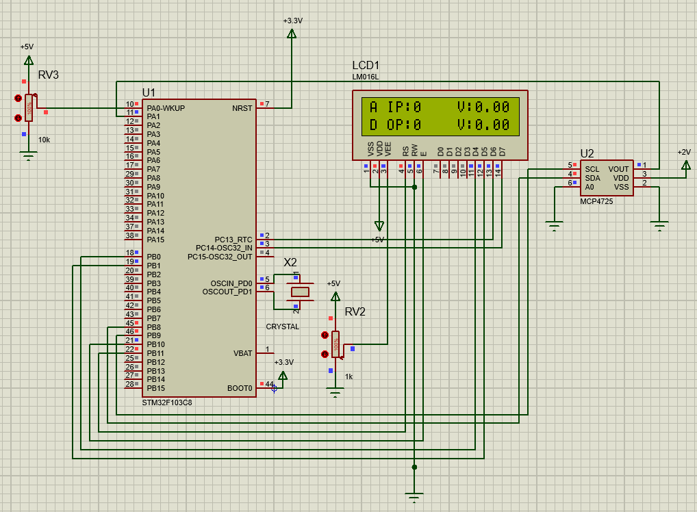
This is the image of the final simulation where it is stuck. even if the rest do not work atleast the result of analogread(PA0) should be displayed. Can someone clear my doubts ?
I have merged your topics due to them having too much overlap on the same subject matter @sbhanot030.
In the future, please only create one topic for each distinct subject matter and be careful not to cause them to converge into parallel discussions.
The reason is that generating multiple threads on the same subject matter can waste the time of the people trying to help. Someone might spend a lot of time investigating and writing a detailed answer on one topic, without knowing that someone else already did the same in the other topic.
Do you see anything on display? At least a text "STM32F103C8" and "DAC with MCP4725"?
If not, that your display code and connections are wrong. In that case it is pointless to test MCP4725 code, you should get to work display first. Try the examples of display library until you see the text in display.
The text is displayed and if I replace analogRead command with some constant value then also the result is displayed on the LCD screen, its just that analogRead command is not working
In your schematic you shown potentiometer connected between 5v and GND. Don't you know that STM32 mcu uses 3.3v logic? And, therefore, its analog input range is 0-3.3v only? Supplying 5V to the analog input may cause damage of the mcu port.
Connect your potentiometer to 3.3v rather than 5v, change the input port to another pin(because you perhaps fried PA0 already) and try again.
I am not sure about this since I got the code from somewhere, but I believe it to related to the I2C communication method I was using to transmit data.
Also There is one point essentially which is not working according to me, that is the code on execution does not take a user defined input(in this case would be the potentiometer) but takes fixed input fed directly into the code. Is there any way that I can resolve this ?
#include <Arduino.h>
//#include<Wire.h>                    //Include Wire library for using I2C functions
//#include<SoftWire.h>
#include <LiquidCrystal.h>          //Include LCD library for using LCD display functions
#define MCP4725 0x60                //MCP4725 address as 0x60 Change yours accordingly
const int rs = PB11, en = PB10, d4 = PB0, d5 = PB1, d6 = PC13, d7 = PC14;
int inp_1 = PA0;
int inp_2 = PA1;
int op = PB9;
LiquidCrystal lcd(rs, en, d4, d5, d6, d7);
unsigned int adc;
unsigned int dac;
//byte buffer[3];                 #include <Arduino.h>
#line 1 "C:\\Users\\Admin\\Documents\\Arduino\\DAC_CODEv2\\DAC_CODEv2.ino"
//#include<Wire.h>                    //Include Wire library for using I2C functions
//#include<SoftWire.h>
#include <LiquidCrystal.h>          //Include LCD library for using LCD display functions
#define MCP4725 0x60                //MCP4725 address as 0x60 Change yours accordingly
const int rs = PB11, en = PB10, d4 = PB0, d5 = PB1, d6 = PC13, d7 = PC14;
int inp_1 = PA0;
int inp_2 = PA1;
int op = PB9;
LiquidCrystal lcd(rs, en, d4, d5, d6, d7);
unsigned int adc;
unsigned int dac;
//byte buffer[3];

void setup()
{
  pinMode(PA0,INPUT_ANALOG);
  pinMode(PA1,INPUT_ANALOG);
  pinMode(PB9, OUTPUT);
  Serial.begin(9600);
//  Wire.begin();                     //Begins the I2C communication
  lcd.begin(16,2);                  //Sets LCD in 16X2 Mode
  lcd.setCursor(0,0);
  lcd.print("STM32F103C8");
  lcd.setCursor(0,1);
  lcd.print("DAC with MCP4725");
  delay(500);
  lcd.clear();
}
void loop()
{
  //buffer[0] = 0b01000000;           //Sets the buffer0 with control byte (010-Sets in Write mode)
  adc = 5000;// resistor value from rheostat        Read Analog value from pin PA0
  float ipvolt = (3.3/4096.0)* adc; //Finding voltage formula
  analogWrite(op, ipvolt);
  dac = 500;//resistor value from rheostat    Reads analog value from PA1
  float opvolt = (3.3/4096.0)* dac; //Finding Voltage Formula
  //Wire.beginTransmission(MCP4725);  //Joins I2C bus with MCP4725 with 0x60 address
  //Wire.write(buffer[0]);            //Sends the control byte to I2C
  //Wire.write(buffer[1]);            //Sends the MSB to I2C
  //Wire.write(buffer[2]);            //Sends the LSB to I2C
  //Wire.endTransmission();           //Ends the transmission
  lcd.setCursor(0,0);
  lcd.print("A IP:");
  lcd.print(adc);                   //Prints the ADC value from PA0
  lcd.setCursor(10,0);
  lcd.print("V:");                  //Prints the Input Voltage at PA0
  lcd.print(ipvolt);
  lcd.setCursor(0,1);
  lcd.print("D OP:");
  lcd.print(dac);                    //Prints the ADC value from PA1 (From DAC)
  lcd.setCursor(10,1);
  lcd.print("V:");
  lcd.print(opvolt);                 //Prints the Input Voltage at PA1 (From DAC)
}
This code works fine where I have already defined the input values. but when I take the value from the rheostat through analogRead command it does not work