Code help: combining 2 sets of codes

Ok here is a gif Imgur: The magic of the Internet (the top 2 rows) of what I want to do. I have several more graphs that I'd like to do but I want to get one graph working.

My prototype setup is
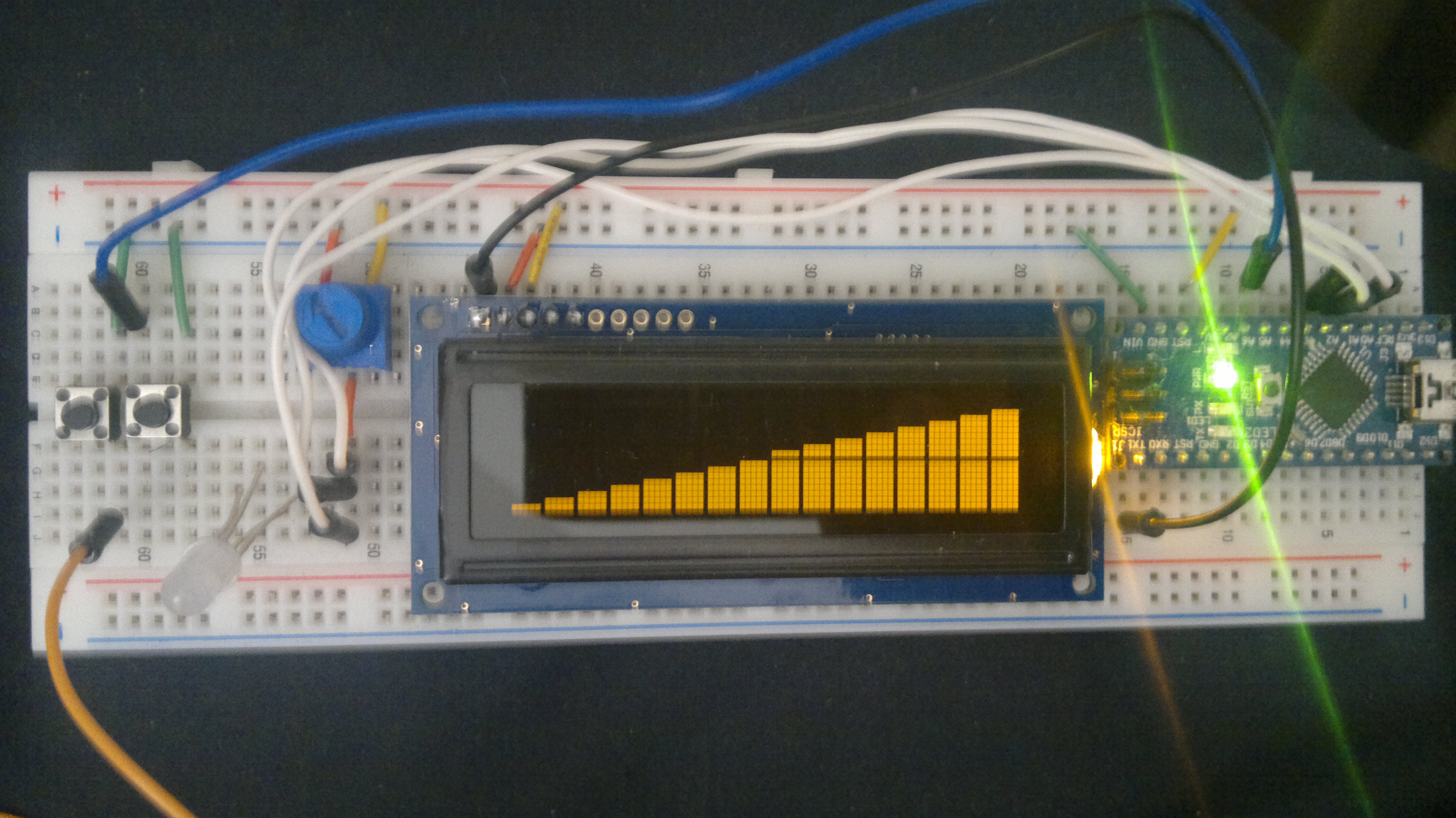
Ardunio Uno with a 2x16 serial LCD

My production setup will be
Ardunio Nano with a 2x20 Serial VFD

I've got all of the custom characters (just blocks) in the ramp I want (see code below).

#include <SerialLCD.h>
#include <Wire.h>

// make some custom characters:
byte P8[8] = {
  0b11111,
  0b11111,
  0b11111,
  0b11111,
  0b11111,
  0b11111,
  0b11111,
  0b11111,
};

byte P7[8] = {
  0b00000,
  0b11111,
  0b11111,
  0b11111,
  0b11111,
  0b11111,
  0b11111,
  0b11111,
};

byte P6[8] = {
  0b00000,
  0b00000,
  0b11111,
  0b11111,
  0b11111,
  0b11111,
  0b11111,
  0b11111,
};

byte P5[8] = {
  0b00000,
  0b00000,
  0b00000,
  0b11111,
  0b11111,
  0b11111,
  0b11111,
  0b11111,
};

byte P4[8] = {
  0b00000,
  0b00000,
  0b00000,
  0b00000,
  0b11111,
  0b11111,
  0b11111,
  0b11111,
};

byte P3[8] = {
  0b00000,
  0b00000,
  0b00000,
  0b00000,
  0b00000,
  0b11111,
  0b11111,
  0b11111,
};

byte P2[8] = {
  0b00000,
  0b00000,
  0b00000,
  0b00000,
  0b00000,
  0b00000,
  0b11111,
  0b11111,
};

byte P1[8] = {
  0b00000,
  0b00000,
  0b00000,
  0b00000,
  0b00000,
  0b00000,
  0b00000,
  0b11111,
};
;

// Constructor.  Parameters: rows, columns, baud/i2c_address, interface (RS232, I2C, SPI)
SerialLCD lcd(2,16,9600,RS232);

void setup() {
  
  // Initialize LCD module
  lcd.init();
    // create a new character
      lcd.createChar(0, P1);
      lcd.createChar(1, P2);
      lcd.createChar(2, P3);
      lcd.createChar(3, P4);
      lcd.createChar(4, P5);
      lcd.createChar(5, P6);
      lcd.createChar(6, P7);
      lcd.createChar(7, P8);
      // Set Contrast
      lcd.setContrast(40);
      // Set Backlight
      lcd.setBacklightBrightness(2);
}

void loop() {
  int i;
 lcd.home();
 // lcd.clear();
  lcd.setCursor(1, 9); // location of the first row cursor
     lcd.write((byte)0);
     lcd.write((byte)1);
     lcd.write((byte)2);
     lcd.write((byte)3);
     lcd.write((byte)4);
     lcd.write((byte)5);
     lcd.write((byte)6);
     lcd.write((byte)7);
 
   lcd.setCursor(2, 1); // location of the second row cursor
     lcd.write((byte)0);
     lcd.write((byte)1);
     lcd.write((byte)2);
     lcd.write((byte)3);
     lcd.write((byte)4);
     lcd.write((byte)5);
     lcd.write((byte)6);
     lcd.write((byte)7);
     lcd.write((byte)7);
     lcd.write((byte)7);
     lcd.write((byte)7);
     lcd.write((byte)7);
     lcd.write((byte)7);
     lcd.write((byte)7);
     lcd.write((byte)7);
     lcd.write((byte)7);
}

This is my stab at the analog pins. The math is about right but getting it to scale with the graph above hasn't worked well for me.

#define lenght 16.0
 double percent=100.0;
 unsigned char b;
 unsigned int peace;
 
#include <SerialLCD.h>
#include <Wire.h>

// make some custom characters:
byte P8[8] = {
  0b11111,
  0b11111,
  0b11111,
  0b11111,
  0b11111,
  0b11111,
  0b11111,
  0b11111,
};

byte P7[8] = {
  0b00000,
  0b11111,
  0b11111,
  0b11111,
  0b11111,
  0b11111,
  0b11111,
  0b11111,
};

byte P6[8] = {
  0b00000,
  0b00000,
  0b11111,
  0b11111,
  0b11111,
  0b11111,
  0b11111,
  0b11111,
};

byte P5[8] = {
  0b00000,
  0b00000,
  0b00000,
  0b11111,
  0b11111,
  0b11111,
  0b11111,
  0b11111,
};

byte P4[8] = {
  0b00000,
  0b00000,
  0b00000,
  0b00000,
  0b11111,
  0b11111,
  0b11111,
  0b11111,
};

byte P3[8] = {
  0b00000,
  0b00000,
  0b00000,
  0b00000,
  0b00000,
  0b11111,
  0b11111,
  0b11111,
};

byte P2[8] = {
  0b00000,
  0b00000,
  0b00000,
  0b00000,
  0b00000,
  0b00000,
  0b11111,
  0b11111,
};

byte P1[8] = {
  0b00000,
  0b00000,
  0b00000,
  0b00000,
  0b00000,
  0b00000,
  0b00000,
  0b11111,
};

;


// Constructor.  Parameters: rows, columns, baud/i2c_address, interface (RS232, I2C, SPI)
SerialLCD lcd(2,16,9600,RS232);

void setup() {
  
  // Initialize LCD module
  lcd.init();
  delay(100);
    // create a new character
  lcd.createChar(0, P1);
  lcd.createChar(1, P2);
  lcd.createChar(2, P3);
  lcd.createChar(3, P4);
  lcd.createChar(4, P5);
  lcd.createChar(5, P6);
  lcd.createChar(6, P7);
  lcd.createChar(7, P8);
  lcd.setCursor(0, 0);
  // Set Contrast
  lcd.setContrast(40);
  // Set Backlight
  lcd.setBacklightBrightness(4);
}

void loop() {
  int i;
 lcd.setCursor(1,1);
 // ADC Conversion
 unsigned int value = analogRead(0);
 percent = value/1024.0*100.0;
  
 // lcd.print(value);
 lcd.print("FUEL ");
 
 // lcd.print(" - ");
 
 lcd.print(value);
 lcd.print(" ");
 
 lcd.setCursor(2,5);
 
 double a=lenght/100*percent;
 
 // Drawing rectangles on LCD
  // drawing black rectangles on LCD
	 
	  if (a>=1) {
	 
	    for (int i=1;i<a;i++) {
	 
	      lcd.write(7);
	 
	      b=i;
	    }
	 
	    a=a-b;
	 
	  }
	 
	  peace=a*5;
	 
	// drawing charater's colums
	 
	  switch (peace) {
	 
	  case 0:
	     break;
	 
	  case 1:
	    lcd.print((char)0);
	    break;
	 
	  case 2:
	    lcd.print((char)1);
	    break;
 
	  case 3:
	    lcd.print((char)2);
	    break;
	 
	  case 4:
	    lcd.print((char)3);
	    break;
	 
	  }
	 
	//clearing line
	  for (int i =0;i<(lenght-b);i++) {
	 
	    lcd.print(" ");
	  }
	 
	  ;

}

what am I missing (I know, alot) I just want it to bar graph like in the GIF. I'm close yet so far. Any help will be appreciated

  int i;

What's this for?

 lcd.setCursor(2,5);

Put the cursor on line 3 of the 2 line LCD. Well, OK.

This is my stab at the analog pins. The math is about right but getting it to scale with the graph above hasn't worked well for me.

The code does something. We can't see what that is. You want the code to do something. It's hard to see from that tiny movie what that is. I think the ball's back in your court.

The int i; I don't know but the screen seems to refresh better when it's in. I'll research it.

lcd.setCursor(2,5); I know, weird. When I set it to 1,5 it goes on top of the first line or 0,5 it doesn't show up at all.

On the GIF if you open it and hold the CTRL+Scroll up it will make the GIF larger. Here is a video in action Arduino cts v boost/afr gauge - YouTube

The video shows a 4x20 LCD, but I want ramp graph of the first 2 rows. In effect I want to do the exact same thing he's doing.

In effect I want to do the exact same thing he's doing.

So, now we know what you want to do. What are you actually doing?

I build custom cars and I hate those typical round gauges that most people use. This project to replace those gauges and to learn Arduino for some other projects I have plan for this car and others.

This will eventually be one graph of several that will be in a menu type of setup. a button press shows the status of Fuel pressure, another button press shows Oil pressure, and so on. I have about 5 things I want to monitor / change from height of the car (it's on air bags) to supercharger temps.

Yes I know there are ODBII shields and stuff but this is totally separate since none of what I want to do is monitored by ODBII.

If I ask you what size shoe you wear, are you going to tell me about the last opera you attended? Is it so difficult to actually answer the questions that are asked?

What does the code you have now ACTUALLY do? It doesn't matter that you don't like round gauges or sugar in your coffee.

HAh, I'm sorry

I want exactly what is in the video (the first two rows. with the ramp). To display the output of AnalogRead pin in a ramp graph style on the LCD. I've got the sketch to do the interger math for the read pin and the sketch to do the custom characters for the ramp graph. Just havent had the skill to get the two to work together.

I don't understand. Did you enjoy the opera, or not?

The first set of codes are the customchar for the ramp, thats it. The second code sample has just blocks on the 2nd row that cheages when the value of AnalogRead changes.

Basically

Code dump 1 looks very close to like video with all the CustomChar but doesn't function
Code dump 2 Functions very close to the video but doesn't look anything like the video with the Ramp graph

Code dump 1 looks very close to like video with all the CustomChar but doesn't function

It might be me, but I'm missing something here. How can the result of running the code look like the video AND not function? It either looks like the video or it doesn't. The code isn't designed to do anything except display a static image. Is that what you mean by "doesn't function"?

Code dump 2 Functions very close to the video but doesn't look anything like the video with the Ramp graph

I still don't know what it does look like.

PaulS:

Code dump 1 looks very close to like video with all the CustomChar but doesn't function

It might be me, but I'm missing something here. How can the result of running the code look like the video AND not function? It either looks like the video or it doesn't. The code isn't designed to do anything except display a static image. Is that what you mean by "doesn't function"?

Correct. I felt I needed to learn CustomChar and how they display thus I got it to look just like the video but it's not functional.

Code dump 2 Functions very close to the video but doesn't look anything like the video with the Ramp graph

I still don't know what it does look like.

Here's a shot of what the second code looks like now. The bottom bar moves as the counts change as I change the blue POT next to the LCD. Turn the pot clockwise and the bar graph moves to the left, turn it counter clockwise and it moves down to the right.

Could you post a picture of the first code in action? I can't see how it produces a ramp. Each custom character is a box, though the boxes are different sizes.

PaulS:
Could you post a picture of the first code in action? I can't see how it produces a ramp. Each custom character is a box, though the boxes are different sizes.

OK. We're almost there. One more picture, with the 2nd code running, and a different value selected, please.

I think that the issue is that you want to display two different "values" on the two rows. The bottom row will display a "value" from 0 to 15, and the top row will display a value from 8 to 15. The "value" to display on each row is a function of the reading from the sensor. Displaying a "value" means to display some number of characters, from 0 to 15 on the bottom row, and some number of characters on the top row. The specific character to display is a function of the column that the character is in. On the bottom row, you'd display character 0 in column 0, character 1 in column 1, etc, up to character 7 in column 7. After that, if something is to be displayed, you'd display character 7.

For the top row, character 0 goes in column 8, character 1 goes in column 9, etc.

PaulS:
OK. We're almost there. One more picture, with the 2nd code running, and a different value selected, please.

I think that the issue is that you want to display two different "values" on the two rows. The bottom row will display a "value" from 0 to 15, and the top row will display a value from 8 to 15. The "value" to display on each row is a function of the reading from the sensor. Displaying a "value" means to display some number of characters, from 0 to 15 on the bottom row, and some number of characters on the top row. The specific character to display is a function of the column that the character is in. On the bottom row, you'd display character 0 in column 0, character 1 in column 1, etc, up to character 7 in column 7. After that, if something is to be displayed, you'd display character 7.

For the top row, character 0 goes in column 8, character 1 goes in column 9, etc.

Here are the pictures.


HMM so you're saying you basically that I need two instances of the bar graph one that starts at say 0,8 on the first row and one that starts at 1,0 on the second row, and each row has it's own value to start at but all reading from the same AnalogRead pin.

HMM so you're saying you basically that I need two instances of the bar graph one that starts at say 0,8 on the first row and one that starts at 1,0 on the second row, and each row has it's own value to start at but all reading from the same AnalogRead pin.

I think that the simplest way to deal with your code is to map the analogRead() value from 0 to 1023 to 0 to 16. Then,
if the mapped value is greater than 8, subtract 8 and use the result to determine what to do on row 0. Then, use the mapped value to determine what to do on row 1.

Start with a switch statement:

switch(mappedValue)
{
   case 15::
      // show character 7 in column 15
   case 14:
      // show character 7 in column 14
   case 13:
      // show character 7 in column 13
   case 12:
      // show character 7 in column 12
   case 11:
      // show character 7 in column 11
   case 10:
      // show character 7 in column 10
   case 9:
      // show character 7 in column 9
   case 8:
      // show character 7 in column 8
   case 7:
      // show character 7 in column 7
   case 6:
      // show character 6 in column 6
   case 5:
      // show character 5 in column 5
   case 4:
      // show character 4 in column 4
   case 3:
      // show character 3 in column 3
   case 2:
      // show character 2 in column 2
   case 1:
      // show character 1 in column 1
   case 0:
      // show character 0 in column 0
}

Notice that there are no break statements. When a case is entered, all subsequent cases should be executed, too. That is why the cases are in decreasing order.

A similar approach for row 0, with only 8 cases, starting at 15 decreasing to 8 will be needed. The difference is which character to display in column n.

Ok I took your sample code and broke it a little just to see what it does. Here is what I'm working with just for the moment

/*
  NKC Electronics serial display - Demo
 
 Demonstrates different functions of the Serial LCD module
 
  The circuit:
 * LCD SCL pin to Arduino SCL pin or Analog 5
 * LCD SDA pin to Arduino SDA pin or Analog 4
 * LCD VSS pin to GND
 * LCD VDD pin to +5V
 */
 #define lenght 16.0
 double percent=100.0;
 unsigned char b;
 unsigned int peace;
 
#include <SerialLCD.h>
#include <Wire.h>

// make some custom characters:


byte P1[8] = {
  0b10000,
  0b10000,
  0b10000,
  0b10000,
  0b10000,
  0b10000,
  0b10000,
  0b10000,
};


byte P2[8] = {
  0b11000,
  0b11000,
  0b11000,
  0b11000,
  0b11000,
  0b11000,
  0b11000,
  0b11000,
};


byte P3[8] = {
  0b11100,
  0b11100,
  0b11100,
  0b11100,
  0b11100,
  0b11100,
  0b11100,
  0b11100,
};


byte P4[8] = {
  0b11110,
  0b11110,
  0b11110,
  0b11110,
  0b11110,
  0b11110,
  0b11110,
  0b11110,
};


byte P5[8] = {
  0b11111,
  0b11111,
  0b11111,
  0b11111,
  0b11111,
  0b11111,
  0b11111,
  0b11111,
};


;


// Constructor.  Parameters: rows, columns, baud/i2c_address, interface (RS232, I2C, SPI)
SerialLCD lcd(2,16,9600,RS232);

void setup() {
  
  // Initialize LCD module
  lcd.init();
  delay(100);
    // create a new character
  // lcd.createChar(0, P1);
  // lcd.createChar(1, P2);
  // lcd.createChar(2, P3);
  // lcd.createChar(3, P4);
  // lcd.createChar(4, P5);
  // lcd.setCursor(0, 0);
  lcd.createChar(0, P1);
  lcd.createChar(1, P2);
  lcd.createChar(2, P3);
  lcd.createChar(3, P4);
  lcd.createChar(4, P5);
  lcd.setCursor(1, 4);
  
  
  // Set Contrast
  lcd.setContrast(40);
  // Set Backlight
  lcd.setBacklightBrightness(4);
}

void loop() {
  int i;
 lcd.setCursor(1,1);
 // ADC Conversion
 unsigned int value = analogRead(0);
 percent = value/1024.0*100.0;
  
 // lcd.print(value);
 lcd.print("FUEL");
 
 // lcd.print(" - ");
 
// lcd.print(percent);
// lcd.print(" % ");
 
 lcd.setCursor(2,5);
 // lcd.setCursor(1,8);
 
 double a=lenght/100*percent;
 
 // Drawing rectangles on LCD
  // drawing black rectangles on LCD
	 
	  if (a>=1) {
	 
	    for (int i=1;i<a;i++) {
	 
	      lcd.write(4);
	 
	      b=i;
	    }
	 
	    a=a-b;
	 
	  }
	 
	  peace=a*5;
	 
	// drawing charater's colums
	 
	  switch (peace) 
{
	 
//	   case 15::
      // show character 7 in column 15
//   case 14:
      // show character 7 in column 14
//   case 13:
      // show character 7 in column 13
//   case 12:
      // show character 7 in column 12
//   case 11:
      // show character 7 in column 11
//   case 10:
      // show character 7 in column 10
//   case 9:
      // show character 7 in column 9
//   case 8:
      // show character 7 in column 8
//   case 7:
      // show character 7 in column 7
//   case 6:
      // show character 6 in column 6
//   case 5:
      // show character 5 in column 5
   case 4:
      // show character 4 in column 4
   case 3:
      // show character 3 in column 3
   case 2:
      // show character 2 in column 2
   case 1:
      // show character 1 in column 1
   case 0:
      // show character 0 in column 0	 
   ;}
	 
	//clearing line
	  for (int i =0;i<(lenght-b);i++) {
	 
	    lcd.print(" ");
	  }
	 
	  
  }

Now the bar graph goes up with one solid bar instead of of one line 5 times to make a block. Which is fine, I think it's the only way to do it.

Now I need to add a bar graph that cursor starts at 0,6 but doesn't display till 500 then goes on to 1024.
then to get the CustomChar so it looks like a ramp.