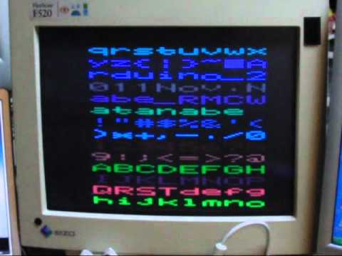
Here's a new code, it has only one color, but handles 21x32 tiles on the screen. Each tile is a 7 byte icon stored in flash, so you can have a lot of icons in flash, not RAM. The problem now is that the code needs more optimizations and also if I try to change the memory data for the tiles in real-time, the video goes out of sync. I need to figure out why.
Edit: I also changed the connections, I'm using SPI for the video output now.
/*

  For connections, use:

  Pin 9 = HZync (PWM) = VGA Pin 13
  Pin 8 = VSync = VGA Pin 14
  Pin 11 = RGB Video (SPI) = VGA Pins 1, 2 & 3 (or use just one to get a single color)

  Ground the following pins on the VGA connector: 6 and 10

  VSync us
  64    - Sync   = 1024 cycles
  1020  - Blank  = 16320 cycles
  15240 - Lines  = 243840 cycles
  350   - Blank  = 5600 cycles

	266784 = cycles total (60 times per second = 60hz)

  HSync us (Lines)
  3.77  - Sync   = 60.32 cycles
  1.89  - Blank  = 30.24 cycles
  25.17 - RGB    = 402.72 cycles
  0.94  - Blank  = 15.04 cycles

	  508 Cycles per line

  VSync Start = 2 lines
  Vsync blank = 32 lines
   480 lines
  VSync Blank = 11 lines

  Total of 525 lines

*/

#include <SPI.h>
#include <avr/pgmspace.h>
#include <avr/sleep.h>
volatile unsigned int linecount;

#define vSyncLow PORTB &= ~(1 << 0);
#define vSyncHigh PORTB |= (1 << 0);

uint8_t tileData[34*21]; // 714 bytes

void setup()
{
  set_sleep_mode(SLEEP_MODE_IDLE);

  pinMode(11, OUTPUT);
  pinMode(8, OUTPUT); // VZync = VGA Pin 14
  pinMode(9, OUTPUT); // HZync = VGA Pin 13

  digitalWrite(8, LOW);
  digitalWrite(11, LOW);

  SPI.begin();
  SPI.setClockDivider(SPI_CLOCK_DIV2);
  SPI.setDataMode(0x04);

  memset(tileData,1,sizeof(tileData));
  tileData[0] = tileData[3] = 0;
  tileData[9] = tileData[12] = 2;
  tileData[21] = tileData[21*3] = 0;
  tileData[21+7] = tileData[(21+7)*3] = 3;

  // Disable Arduino Timer0 and UART Timer
  TCCR0A = TCCR0B = 0;
  TIMSK0 = 0;

  TCCR1A =  _BV(COM1A1) | _BV(COM1A0) | _BV(WGM11);
  TCCR1B = _BV(WGM12) | _BV(WGM13) | _BV(CS10); // No Prescalar
  ICR1 = 508;
  TIMSK1 = _BV(TOIE1); // Enable timer overflow interrupt
  OCR1A = 60; // HSync Pulse

  sei(); // enable global interrupts
}

uint8_t y = 0;
uint8_t y2 = 0;
uint8_t temp = 0;
int line21 = 0;
extern PROGMEM prog_uchar charData[];
#define topOffset 39

void loop()
{
  if (linecount >= topOffset && line21 < (34*21))
  {
    sleep_mode();
    temp = pgm_read_byte_near(charData + (tileData[0+line21]*7) + y);
    SPDR = temp; temp = pgm_read_byte_near(charData + (tileData[1+line21]*7) + y);
    SPDR = temp; temp = pgm_read_byte_near(charData + (tileData[2+line21]*7) + y);
    SPDR = temp; temp = pgm_read_byte_near(charData + (tileData[3+line21]*7) + y);
    SPDR = temp; temp = pgm_read_byte_near(charData + (tileData[4+line21]*7) + y);
    SPDR = temp; temp = pgm_read_byte_near(charData + (tileData[5+line21]*7) + y);
    SPDR = temp; temp = pgm_read_byte_near(charData + (tileData[6+line21]*7) + y);
    SPDR = temp; temp = pgm_read_byte_near(charData + (tileData[7+line21]*7) + y);
    SPDR = temp; temp = pgm_read_byte_near(charData + (tileData[8+line21]*7) + y);
    SPDR = temp; temp = pgm_read_byte_near(charData + (tileData[9+line21]*7) + y);
    SPDR = temp; temp = pgm_read_byte_near(charData + (tileData[10+line21]*7) + y);
    SPDR = temp; temp = pgm_read_byte_near(charData + (tileData[11+line21]*7) + y);
    SPDR = temp; temp = pgm_read_byte_near(charData + (tileData[12+line21]*7) + y);
    SPDR = temp; temp = pgm_read_byte_near(charData + (tileData[13+line21]*7) + y);
    SPDR = temp; temp = pgm_read_byte_near(charData + (tileData[14+line21]*7) + y);
    SPDR = temp; temp = pgm_read_byte_near(charData + (tileData[15+line21]*7) + y);
    SPDR = temp; temp = pgm_read_byte_near(charData + (tileData[16+line21]*7) + y);
    SPDR = temp; temp = pgm_read_byte_near(charData + (tileData[17+line21]*7) + y);
    SPDR = temp; temp = pgm_read_byte_near(charData + (tileData[18+line21]*7) + y);
    SPDR = temp; temp = pgm_read_byte_near(charData + (tileData[19+line21]*7) + y);
    SPDR = temp; temp = pgm_read_byte_near(charData + (tileData[20+line21]*7) + y);
    SPDR = temp;

    y2++;
    if (y2 == 2)
    {
      y2 = 0;
      y++;
      if (y == 7)
      {
        y = 0; line21 += 21;
      }
    }
  }
  else if (linecount == 0)
  {
    y = y2 = temp = line21 = 0;
  }
}

ISR(TIMER1_OVF_vect)
{
  if (linecount == 0) vSyncLow;
  if (linecount == 2) vSyncHigh;
  if (++linecount == 525) linecount = 0;
}
And the symbols-test:
#include <avr/pgmspace.h>

PROGMEM prog_uchar charData[7*4] = {
B11000110,
B11000110,
B11100110,
B11101110,
B00111000,
B00010000,
B00000000,

B00010000,
B01101100,
B11000110,
B11000110,
B01101100,
B00111000,
B00000000,

B11111110,
B11111110,
B11111110,
B11111110,
B00111000,
B00010000,
B00000000,

B00010000,
B01111100,
B11111110,
B11111110,
B01111100,
B00111000,
B00000000};
 Will try to check this tomorrow or later on.
 Actually, the signal sync could be possible, but not any image. Handling 640x480 is already pushing the Arduino to its limits, really.

 Great job.