Common Cathode Seven segment display and ATmega328p GPIO pin current question
Hi
I have a common cathode 4-digit 7-seg display which i wish to connect to ATmega328p
Its draws 36mA with 500 ohms current limit resistors. when every pin are on.
(Vs-Vd)/R = I , 5-2.2/500 = 5.6mA * 8 = 44mA.(i have measured this)(everything is working)
Each digit is switched to GND via a GPIO current sink. i.e. connected directly.
I see all over the internet in many reputable places(blogs, tutorials)
people connect the digit control pins straight to the GPIO pins.
It seems to be common practice in the "arduino world"
For example. here on sunfounder site
This is same display I have (.56 common cathode red ) as i got it in a sunfounder Arduino kit
If you use 220 ohm resistors as per their suggestion.
This would mean 101mA is following thru GPIO pin connected to Digit. when all segments are on.
Yet the current Maximum limit of GPIO is 40mA
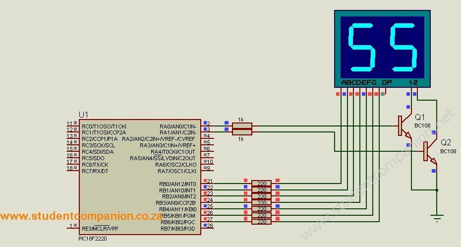
I don't understand normally in PIC world if connecting a Common-cathode 7-seg digit
to PIC you turn on via a transistor like this circuit just for example.
typematrix:
Whats going on? what am I missing here?
Assuming that "tutorials" on the Web are knowledgeable in some way.
People tried something - it "sort of" worked though not well, so they wrote up their findings with a degree of optimism.
Sometimes they even made a module and sold it to unsuspecting buyers!
typematrix:
How can Atmega328p survive this?
It is fairly durable.
Yes, it may fail in time, but overloading it mildly beyond its recommended absolute maxima will not automatically cause catastrophic failure.
Note the limitation in your calculations. You assumed a LED voltage of 1.8 V with a 5 V supply but have not factored in the internal resistance of the drivers in the chip - about 50 Ohm each. This means the actual current is limited to 38 mA by the chip itself and if the multiplexing is functioning, for only one quarter of the time per cathode driver.
Paul__B:
Assuming that "tutorials" on the Web are knowledgeable in some way.
People tried something - it "sort of" worked though not well, so they wrote up their findings with a degree of optimism.
Sometimes they even made a module and sold it to unsuspecting buyers!
Yes, it may fail in time, but overloading it mildly beyond its recommended absolute maxima will not automatically cause catastrophic failure.
Note the limitation in your calculations. You assumed a LED voltage of 1.8 V with a 5 V supply but have not factored in the internal resistance of the drivers in the chip - about 50 Ohm each. This means the actual current is limited to 38 mA by the chip itself and if the multiplexing is functioning, for only one quarter of the time per cathode driver.
I amwell aware of the pitfalls of the net that's why I came here to check, I was struck by just how many sites all had same wiring. I knew from my PIC experience that this was odd.
So wiring a 7-seg is not right.
The multiplexing of the 4 digits does not effect the 100mA figure, which is the draw of one digit with all segments and decimal point on when resistors are 220ohms
Can you show where in the datasheet ATmega328p I/O current is limited by chip to 38mA
I cannot find it. I see on p308 it specifies
DC Current per I/O Pin . . . . . . . . . . . . . . . . . . 40.0mA as a absolute maximum rating.
Yes, the absolute maximum current per I/O pin is 40ma. And the maximum total current is 200ma. I agree with you that even coming close to either number is not good practice. But there are two solutions that would allow you to safely multiplex four digits without using transistors.
The first is to use much more efficient 7-segment displays. I don't know what's available in a four-digit package, but I use the Vishay TDSR1360-IK single digit displays, and they are bright enough for me using 2.2K resistors in a 5V circuit.
The other solution is to multiplex by segment instead of by digit. Here's a video on that:
And the related Github repository with Arduino demonstration sketches:
This method lets you get rid of all the segment resistors and CC transistors, leaving you with only one resistor on each CC line. In theory it does not save on current because having segments turned on only 1/7 of the time should require lower value resistors to achieve the same perceived brightness, but it certainly does save on parts.
typematrix:
The multiplexing of the 4 digits does not effect the 100mA figure, which is the draw of one digit with all segments and decimal point on when resistors are 220ohms
Ah, but it isn't! Not in the circuit you gave.
typematrix:
Can you show where in the datasheet ATmega328p I/O current is limited by chip to 38mA
I cannot find it.
Refer to Figure 27-160 in the datasheet. Note the parameters on the curve - voltage drop at 25 °C is about 0.5 V at 20 mA. This corresponds to 25 Ohms while the corresponding voltage drop on Figure 27-162 is much the same. So I may have been too conservative in stating 50 Ohms.
On this basis, we have eight 220 Ohm resistors in series with another 25 Ohms internal resistance in the drivers, in parallel they are effectively 34 Ohms. In the cathode driver you have another 25 Ohms, total that as 59 Ohms. If the voltage drop of your LEDs is 1.8 V, then you have 3.2 V across these compound resistances and the current through that cathode driver would be - about - 55 mA.
But note that the curves shown are not linear and extend only to 20 mA - at 55 mA, the effective internal resistance of the driver will be significantly greater.
Just to be clear, the LED module I have is larger than the much more common '38 inch, its '56 inch and has a voltage drop of 2.2 volts per segment not 1.8. I calculated with 220ohms resistors ~100mA and I measured on bench that its 96mA (WITHOUT the u-controller connected just manually switched on segments).
typematrix:
WITHOUT the u-controller connected just manually switched on segments
Which is fine, but simply not relevant to connecting it up to a microcontroller, is it?
The calculation above "tweaked" for 2.2 volts across the LEDs would give 47 mA for what it is worth. The size of the display segments has little or nothing to do with it as the LEDs used are entirely unrelated to such minor variations in the display size. (Obviously a really large display might use something different. )
I should perhaps point out that the "take home message" here is not just that you need to re-size the resistors to comfortably work within the microcontroller ratings as obviously you just use 1k resistors to do that. It is rather that because the driver resistance is introduced into the common cathode circuit, the overall display brightness of each digit will visibly vary according to the number of segments simultaneously lit.
And you have to multiplex it efficiently in the program code. This is simply a "toy" exercise. For any serious application, it makes much more sense to use a module based on a MAX7219 which is specifically designed to accommodate all these considerations and do the job perfectly.