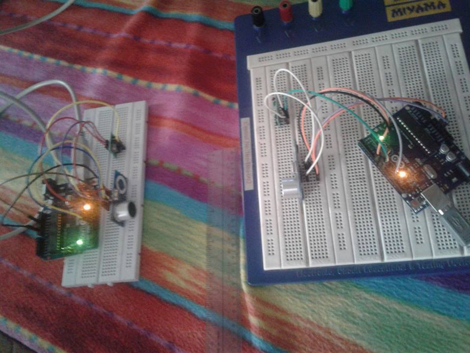
I've put together some code that seems to be working on my test set up. For this, I'm using unmodified HC-SR04 sensors on both nodes, except for covering the "T" transducer on the receiver side, so it should only see the ping sent by the transmitter node.
The 433 MHz OOK sync scheme is as described above, hopefully the code is self-explanatory.
Transmit node sketch:
/*
  Transmit side of one way ultrasonic ranging using HC-SR04.
  Node sync is performed with 433 MHz OOK transmit receive pair via a sync sequence

  HC-SR04 Ping distance sensor:
  VCC to arduino 5v
  GND to arduino GND
  Echo to Arduino pin 7
  Trig to Arduino pin 8

  433 MHz Transmitter:
  Data to Arduino pin 9

  HC-SR04 technique from here: http://arduinobasics.blogspot.com.au/2012/11/arduinobasics-hc-sr04-ultrasonic-sensor.html
*/


#define echoPin 7 // Echo Pin
#define trigPin 8 // Trigger Pin
#define rfTxPin 9 // rf Transmit enable
#define LEDPin 13 // Onboard LED
#define BitPeriod 500   // Bit period for RF sync bits in microseconds

boolean syncSeq[16] = {1, 0, 1, 0, 1, 0, 1, 0, 1, 0, 1, 0, 1, 0, 1, 1} ; // Bit sequence for synchronization

int maximumRange = 200; // Maximum range needed (cm)
int minimumRange = 0; // Minimum range needed
long duration, distance; // Duration used to calculate distance
long timeout = 50000;  // Ping duration timeout (uS)

void setup() {
  Serial.begin (9600);
  pinMode(trigPin, OUTPUT);
  pinMode(echoPin, INPUT);
  pinMode(rfTxPin, OUTPUT);
  pinMode(LEDPin, OUTPUT); // Use LED indicator (if required)
  digitalWrite(trigPin, LOW) ;
  digitalWrite(rfTxPin, LOW) ;
}

void loop() {
  digitalWrite(LEDPin, HIGH);
  TxRFSync() ;        // Send RF synchronization sequence
  digitalWrite(trigPin, HIGH);      // Start ping sequence
  delayMicroseconds(10);
  digitalWrite(trigPin, LOW);
  duration = pulseIn(echoPin, HIGH, timeout);
  digitalWrite(LEDPin, LOW);

  //Calculate the distance (in cm) based on the speed of sound.
  distance = duration / 58.2;

  if (distance >= maximumRange || distance <= minimumRange) {
    /* Send a negative number to computer */
    Serial.println("-1");
  }
  else {
    /* Send the distance to the computer using Serial protocol. */
    Serial.println(distance);
  }

  //Delay 100ms before next reading.
  delay(100);
}

// Function to write "syncSeq" bit sequence to RF transmit port
void TxRFSync()
{
  for (int k = 0; k < sizeof(syncSeq) ; k++)
  {
    digitalWrite(rfTxPin, syncSeq[k]) ;
    delayMicroseconds(BitPeriod) ;
  }
  digitalWrite(rfTxPin, LOW) ;      // Turn off transmit at end of sequence
}
Receive side sketch:
/*
  Receive side of one way ultrasonic ranging using HC-SR04.
  Node sync is performed with 433 MHz OOK transmit receive pair via a sync sequence

  HC-SR04 Ping distance sensor:
  VCC to arduino 5v
  GND to arduino GND
  Echo to Arduino pin 7
  Trig to Arduino pin 8

  433 MHz Receiver:
  Data to Arduino pin 9

  HC-SR04 scheme from here: http://arduinobasics.blogspot.com.au/2012/11/arduinobasics-hc-sr04-ultrasonic-sensor.html
*/
#define syncStateA 10
#define syncStateB 11
#define debugPinC 12

#define echoPin 7 // Echo Pin
#define trigPin 8 // Trigger Pin
#define rfRxPin 9 // rf Receive input pin
#define LEDPin 13 // Onboard LED

// Parameters for sync detection
#define minBitPeriod 450  // Low threshold for bit period (uS)
#define maxBitPeriod 550  // Max threshold for bit period (uS)
#define minSyncBits 8     // Min number of valid 1 plus 0 transitions before 1 plus 1

int maximumRange = 200; // Maximum range needed (cm)
int minimumRange = 0; // Minimum range needed
long duration, distance; // Duration used to calculate distance
long timeout = 50000;  // Ping duration timeout

void setup() {
  pinMode(syncStateA, OUTPUT) ;
  pinMode(syncStateB, OUTPUT) ;
  pinMode(debugPinC, OUTPUT) ;

  Serial.begin (9600);
  pinMode(trigPin, OUTPUT);
  pinMode(echoPin, INPUT);
  pinMode(rfRxPin, INPUT);
  pinMode(LEDPin, OUTPUT) ;
  digitalWrite(LEDPin, LOW) ;
  digitalWrite(trigPin, LOW) ;
}

void loop() {
  RxRFSync() ;    // Function blocks until sync sequence is detected
  digitalWrite(LEDPin,HIGH) ;
  digitalWrite(trigPin, HIGH);    // Start ping sequence
  delayMicroseconds(10);
  digitalWrite(trigPin, LOW);
  duration = pulseIn(echoPin, HIGH, timeout);

  //Calculate the distance (in cm) based on the speed of sound.
  distance = duration / 29.1 ;

  if (distance >= maximumRange || distance <= minimumRange) {
    /* Send a negative number to computer */
    Serial.println("-1");
  }
  else {
    /* Send the distance to the computer using Serial protocol */
    Serial.println(distance);
  }
  digitalWrite(LEDPin,LOW) ;
}

// Function to detect "syncSeq" bit sequence on RF receive port
void RxRFSync()
{
  long int lastBitTime = 0 ;    // holds time of last bit transition (uS)
  int BitCount = 0 ;            // counts number of valid bits detected

  boolean synced = false ;
  boolean lastBit = LOW ;  // holds last bit detected

  digitalWrite(syncStateA, LOW) ; digitalWrite(syncStateB, LOW) ; digitalWrite(debugPinC, LOW) ;

  while (!synced)
  {
    while (digitalRead(rfRxPin) == lastBit) { } // Block until bit transition
    int currBitTime = micros() ;
    int bitPeriod = currBitTime - lastBitTime ;

    if ((bitPeriod > (2 * minBitPeriod)) && (bitPeriod < (2 * maxBitPeriod)) && (lastBit == HIGH) && (BitCount > minSyncBits))
    {
      // Valid completion of sync sequence
      synced = true ;
      digitalWrite(syncStateA, HIGH) ; digitalWrite(syncStateB, HIGH) ; digitalWrite(debugPinC, lastBit) ;
    }
    else
    {
      lastBit = !lastBit ;
      lastBitTime = currBitTime ;
      if ((bitPeriod > minBitPeriod) && (bitPeriod < maxBitPeriod))
      {
        // Valid single bit detected, increment valid bit count and look for next bit
        BitCount += 1 ;     // increment valid bit count
        digitalWrite(syncStateA, LOW) ; digitalWrite(syncStateB, HIGH) ; digitalWrite(debugPinC, lastBit) ;
      }
      else
      {
        // Invalid bit detected, reset valid bit count and look for next bit
        BitCount = 0 ;
        digitalWrite(syncStateA, HIGH) ; digitalWrite(syncStateB, LOW) ; digitalWrite(debugPinC, lastBit) ;
      }
    }
  }
}
Logic analyzer waveforms showing sync, sync debug, and ultrasound trigger and echo. The offset between HC-SR04 trigger on the two nodes is about 55 microseconds which could be improved by removing the debug in RxRFSync() and/or calibrated out with delayMicroseconds: