Complex timers manipulation

Hallo to everybody!

I'm currently in the research stage of a working principle which involves any RLC circuit, trying to harvest their back-emf spikes and store them for future use.

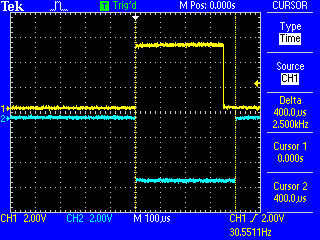
To accomplish that, I thought to an electronic DPDT (for the sake of simplicity an Half-Bridge) which needs an exact pulse sequence: in the attached images you can see the sequence I need to be generated by the Arduino's board (no matter of which board, Uno, Mega or Nano, just to make some tests, the final version - probably - will make use of a miniaturized tailor-made circuit).

I already developed, in the Arduino IDE, a small code to generate a very raw pulse, based on the idea I've drawn in the sketch, and it works beautifully...BUT! There are a couple of issues that I'm still unable to solve (to obtain an incredible gain, my final target):

  • first of all I'm unable to keep the inverted signal (the one in the sketch marked as "Wave B", the red one) narrower than the non-inverted one (Wave A) on-demand (through a multi-turn pot); I exactly know how to read a pot through an analog input, the problem is how to instruct the timers to interpret the read value and change accordingly;
  • the second issue is that, always speaking about the "Wave B", I'm unable to "move/shift" it, to the left or to the right, respect the "Wave A" (to make a delay or to anticipate the fall of the other waveform).

Every change I'll make to the duty cycle (or to the "Wave B"'s position, left/right shift) has to be kept in sync with the "Wave A" 's position & frequency - this is mandatory -.

The frequency of both waves A&B (always in sync) can then vary (with custom intervals, still to be investigated), changing from the fundamental resonant frequency (of the inductor under test) and its upper harmonics (mainly the 3rd but also the 9th).

Please pay attention that the above requirements are distinct:

  • the duty cycle of the "Wave B" (always narrower than the one of the "Wave A") and its relative position, serve exclusively in the setup phase - only once - to test the inductor's reaction to the pulse: the inductor is scoped during the fine tuning (via a multiturn POT) of the duty cycle and its position until the correct arrangement is found (then stored as a constant in the Arduino's code)
  • the varying frequency, from the fundamental resonant frequency and its harmonics, serve to detect the best sequence to be fed into the inductor (e.g.: 4 pulses @ fundamental freq, then 7 pulses @ 3d harmonic, then 3 pulses @ 9th harmonic, back to the fundamental... in a loop) and raise the voltage spikes even more.

That's it.

For me it's a big challenge but, probably, for you it could be a simple game.

Many thanks in advance for your suggestions/thoughts.

Devesh

Dual-inverted-PWM-with-dead-time.png

The problem is in the code you didn't post.

It seems like you are trying to use timers do do something that they aren't intended to do. You probably don't need timers to do this. A simple delayMicroseconds() might do what you need.

Hallo Morgan, thank you for your prompt and kind answer.

Basically I've done this (I'm at office now, so I don't have access to my full code, which is at home):

void setPwm (int val)
{
  OCR1A = val ;
  OCR1B = val ;
  TCCR1A = 0b10110000 | (TCCR1A & 0b00001111) ;
}

And, of course, I've passed the right values to the setPwm function to obtain the requested frequency: my scope displays two exact, opposite, square waves.

The signal's duty cycle, of both the output pins - in this way - is exactly the same, and so the rise/fall starting points... but I need an independent control of each duty cycle to get one signal narrower than the other and/or to anticipate/delay one signal respect to the other, programatically.

A "simple" delayMicroseconds() won't be useful because the "dead time" could be of some nanoseconds (the frequency could be in the order of some MHz: 2 or 3 at maximum).

Any thoughts?

In your image, it mentions deadtime and being able to shift the waveform "few nanoseconds". The best timing resolution possible for this is 62.5ns with a 16MHz MCU.

What is the PWM frequency or range of PWM frequency?

Note that the Arduino Due has PWMC (complimentary PWM) c/w deadtime registers and 11.9ns resolution. It also can be configured to have the PWMC outputs synchronized.

Getting two pulses, one inverted, and centered at the same place is straightforward. You have done that. If you give OCR1A and OCR1B different values, the duty cycles will be different. There are different top values for the pwm modes which along with the prescaler control the frequency.

As dlloyd says, you can at best achieve a 62.5 ns difference on the lead and trailing edge when you want the pulses to be centered at the same place.

because the "dead time" could be of some nanoseconds (the frequency could be in the order of some MHz: 2 or 3 at maximum).

You can't achieve this on a 16MHz processor.

If you want to try your concept with the 62.5 ns difference at the edges, what frequency do you want to be at?

We can make the two signals out of phase easily enough:

void setup()
  {
  // Defining PB1 and PB2 as outputs by setting PORTB1 and PORTB2
  // Setting DDB1 and DDB2
  DDRB |= bit (DDB1) | bit (DDB2);
 
  // stop timer 1
  TCCR1A = 0;
  TCCR1B = 0;
  
  TCCR1A = bit (COM1B0) | bit (COM1B1)  // Set OC1B on Compare Match, clear
                                        // OC1B at BOTTOM (inverting mode)
         | bit (COM1A1)                 // Clear OC1A on Compare Match, set
                                        // OC1A at BOTTOM (non-inverting mode)
         | bit (WGM11);                 // Fast PWM, top at ICR1
  TCCR1B = bit (WGM12)  | bit (WGM13)   //       ditto
         | bit (CS11);                  // Start timer, prescaler of 8

  ICR1 = 0xFFFF;    // period
  OCR1B = 800;      // duty cycle
  OCR1A = OCR1B;    // same duty cycle

  }  // end of setup

void loop()
  {
  }

forum_419374B.png

Note: Output pins are 9 and 10 on the Uno.


And by reducing one of them we can get one shorter than the other:

void setup()
  {
  // Defining PB1 and PB2 as outputs by setting PORTB1 and PORTB2
  // Setting DDB1 and DDB2
  DDRB |= bit (DDB1) | bit (DDB2);
 
  // stop timer 1
  TCCR1A = 0;
  TCCR1B = 0;
  
  TCCR1A = bit (COM1B0) | bit (COM1B1)  // Set OC1B on Compare Match, clear
                                        // OC1B at BOTTOM (inverting mode)
         | bit (COM1A1)                 // Clear OC1A on Compare Match, set
                                        // OC1A at BOTTOM (non-inverting mode)
         | bit (WGM11);                 // Fast PWM, top at ICR1
  TCCR1B = bit (WGM12)  | bit (WGM13)   //       ditto
         | bit (CS11);                  // Start timer, prescaler of 8

  ICR1 = 0xFFFF;    // period
  OCR1B = 800;      // duty cycle
  OCR1A = 700;      // duty cycle

  }  // end of setup

void loop()
  {
  }

forum_419374C.png


However the above shows that the shorter one is not centered. That is because it was fast PWM. By using "phase correct" PWM we get the shorter one centered:

void setup()
  {
  // Defining PB1 and PB2 as outputs by setting PORTB1 and PORTB2
  // Setting DDB1 and DDB2
  DDRB |= bit (DDB1) | bit (DDB2);
 
  // stop timer 1
  TCCR1A = 0;
  TCCR1B = 0;
  
  TCCR1A = bit (COM1B0) | bit (COM1B1)  // Set OC1B on Compare Match, clear
                                        // OC1B at BOTTOM (inverting mode)
         | bit (COM1A1);                // Clear OC1A on Compare Match, set
                                        // OC1A at BOTTOM (non-inverting mode)
  TCCR1B = bit (WGM13)                  //      PWM, top at ICR1
         | bit (CS11);                  // Start timer, prescaler of 8

  ICR1 = 0xFFFF;    // period
  OCR1B = 800;      // duty cycle
  OCR1A = 600;      // duty cycle

  }  // end of setup

void loop()
  {
  }

forum_419374D.png


The rise time is not zero however, as you can see by zooming in. It's around 15 ns (some of that may be measurement error). I don't think you can get much better than that on this processor.

forum_419374A.png

forum_419374B.png

forum_419374A.png

forum_419374C.png

forum_419374D.png

@dlloyd: first of all, thank you so much for your precious advice!

When you said: "The best timing resolution possible for this is 62.5ns with a 16MHz MCU" what did you mean with "the best timing resolution"?

Did you speak about the "deadtime" interval?

So, if I've correctly interpreted your answer, the Arduino Uno Board can only ensure, at its best, a deadtime interval of 62.ns, independently from the frequency?

Wow, it could be a fantastic news for the experiment I'm working on...I have a very big inductance to be stimulated: 13 Henries! With a such low interval time for the deadtime, I'll be able to switch the incoming voltage peak - coming as back-emf - fully into my tank capacitor!!! I'm so happy to hear that (if I've understood correctly, of course...)

@cattledog, dlloyd: the frequency of the PWM pulse I have to inject depends from the inductor I have under test so, in my first experiment for example, I have to put in resonance a 13H/5nF huge inductor so I'll inject a pulse of 624.26 Hertz. But my goal is to build a sort of "Joule Thief" able to run with any kind of inductor.

@Nick Gammon: I'm simply...speachless! You did all the work I needed... A picture of you deserves a place in the middle of my living room!

I didn't expect such incredible help and availability in these days of our epoch, full of terrorism, indifference, loneliness, poverty, injustice and so on. Nick: it is very probable that I'll transfer my whole family to Sidney or Melbourne...really, it's not a joke. When that time will come, I'll offer you an half dozen of exquisite pints of beer.

In the end, thank you all guys: hope the best for everybody and, if I'll succeed with my research, it will be an honor and a pleasure to post here my results.

Fabrizio

So, if I've correctly interpreted your answer, the Arduino Uno Board can only ensure, at its best, a deadtime interval of 62.ns, independently from the frequency?

Not exactly. The lead and trailing edges of the two pulses can differ by one timer count. At the fastest timer settings, prescaler of 1, that one count is equal to 62.5 ns. When the timer is set to run this fast, the frequency of the pulse can not be slower than 1/8.192ms = 122 Hz.

In Nick's third sketch with the out of phase centered pulses he is using a prescaler of 8, and the "deadtime" difference between the pulse edges can only be 0.5 microsecond.

I'll inject a pulse of 624.26 Hertz.

Using the model of Nick's sketch, if you want a dead time of 62.5 ns, the duty cycle values will need to differ by 2, and ICR1 = 12815. To use a prescaler of 1 instead of 8

TCCR1B = bit (WGM13)                  //      PWM, top at ICR1
         | bit (CS10);                  // Start timer, prescaler of 1

@cattledog: your note has been useful; I've tried it and found that, using your advice, I've reduced the dead time to a more reasonable small time. Thank you!

I've also noticed that there is a strict relationship between the period (ICR1) and both the duty cycles (OCR1A & OCR1B): changing the first one will affect the others.

This the code I've tried:

void setup()
  {
  // Defining PB1 and PB2 as outputs by setting PORTB1 and PORTB2
  // Setting DDB1 and DDB2
  DDRB |= bit (DDB1) | bit (DDB2);
 
  // stop timer 1
  TCCR1A = 0;
  TCCR1B = 0;
  
  TCCR1A = bit (COM1B0) | bit (COM1B1)  // Set OC1B on Compare Match, clear
                                        // OC1B at BOTTOM (inverting mode)
         | bit (COM1A1);                // Clear OC1A on Compare Match, set
                                        // OC1A at BOTTOM (non-inverting mode)
  TCCR1B = bit (WGM13)                  //      PWM, top at ICR1
         | bit (CS10);                  // Start timer, prescaler of 1
         
  ICR1 = 0x3000;    // period
  OCR1A = 7000;      // duty cycle
  OCR1B = 6998;      // duty cycle

  }  // end of setup

void loop()
  {
  }

The above will result in a 650Hz pulse, with a duty cycle of 51% (PIN9) and 49% (PIN10) which is very near to what I'm trying to achieve; both the waves are perfectly in sync and centered at the middle point, with a dead time between the edges of approx 200ns; not perfect but it's a start.

The problem I noticed in this configuration is that I can't go higher than 650Hz!

When I try to reduce the ICR1's value below 0x3000 (which gave me the above frequency), everything stops and no signal comes out from the output pins (9&10): in this way I won't be able to sweep the frequency to the higher harmonics I need (the 3rd and the 9th) which are, respectively, 1872Hz and 5618Hz.

I need to understand the relationship between these three timer's registers (ICR1, OCR1A, OCR1B) prior to start coding the ISRs routines (on a different timer, of course) which will allow me to read my digital pots and apply their variable values to the above timer's registers accordingly.

A further help will be appreciated a lot.

Fabrizio

The frequency is controlled by ICR1. The lower that is (that is, the lower the period) the higher the frequency. Then the other two figures (OCR1A and OCR1B) must be within that. You can't have a period of 2000 and a duty cycle of 3000. The duty cycle is never reached in that case.

So, for ICR1 = 1000 you get a frequency of 8 kHz.

 1 / (62.5e-9 * 1000) / 2 = 8000

You divide by two because of the way that phase-correct PWM works.

Basically, for a 50% duty cycle OCR1A and OCR1B should be half of ICR1.

The above will result in a 650Hz pulse, with a duty cycle of 51% (PIN9) and 49% (PIN10) which is very near to what I'm trying to achieve; both the waves are perfectly in sync and centered at the middle point, with a dead time between the edges of approx 200ns; not perfect but it's a start.

Your numbers don't quite work out correctly.

ICR1 = 0x3000 is decimal 12288 and there will be a total of 24576 timer counts of .0625us = 1.536 ms before reset. Calculates to frequency 651, so 650 is close enough given the accuracy of the Arduino internal oscillator.

The duty cycles should be 7000/12288 = 56.97% and 6998/12288 = 56.95%. This is using the visualization that the inverted duty cycle is "shorter" than the non inverted.

The theoretical "dead time" or difference between the edges of the two pulses should be 62.5 ns. Given the ringing and slope seen in the lead edges in Nicks image, I'm not sure how you measure the 200 ns difference.

When I try to reduce the ICR1's value below 0x3000 (which gave me the above frequency), everything stops and no signal comes out from the output pins (9&10)

You can not have the ICR1 value less the OCR1A and OCR1B values. Or, expressing it the other way round, OCR1A and OCR1B can not be larger than ICR1.

For 1872 Hz ICR1 should be 4273 and for 5618 Hz ICR1 is 1423 so you can not be using the 7000 and 6988 for duty cycle.

EDIT: I see that Nick just beat me to it.

@Nick & cattledog: dear guys, thanks to your precious information I've reached my goal. Following, there is the code, comprehensive of the digital encoder's ( KY-040 Rotary Encoder Module) control, to manage the signals I was looking for.

/*
 * Electronic DPDT
 * by Fabrizio Ricciarelli - 2016 A.D.
 * (with the precious advises given by Nick Gammon, cattledog and dlloyd, from the offical Arduino Forum - http://forum.arduino.cc/)
 *
  WIRING INFORMATION
  ===================
  POT A
  Connect CLK to Pin 2 on Arduino Board  (CLK is Data Output 1 of KY-040)
  Connect DT  to Pin 4 on Arduino Board  (DT is Data Output 2 of KY-040)
  Connect SW  to Pin 5 on Arduino Board  (Switch - goes LOW when pressed)

  POT B
  Connect CLK to Pin 3 on Arduino Board  (CLK is Data Output 1 of KY-040)
  Connect DT  to Pin 6 on Arduino Board  (DT is Data Output 2 of KY-040)
  Connect SW  to Pin 7 on Arduino Board  (Switch - goes LOW when pressed)

  BOTH POTS
  Connect GND to ground
  Connect +   to +5V  (this will pull up CLK and DT with 10 KiloOhm resistors)
  ----------------------------------------------------------------------------
  Connect a 0,47µ capacitor from ground to CLK (debouncing) 1 uF it's working fine
  Connect a 0,47µ capacitor from ground to DT (debouncing) 1 uF it's working fine
  Connect a 0,47µ capacitor from ground to SW (debouncing) 1 uF it's working fine
  Connect a 10 KOhm resistor from +5V to SW (no integrated pullup for SW !!)
  ----------------------------------------------------------------------------
  It is better NOT to use internal pull-up resistors on the Arduino, instead
  use the integrated pull-ups of KY-040 (this requires "+" to be connected to 5V).
  You can check if your version of the KY-040 has pull-up resistors on the bottom
  side of the printed circuit board.
  If not, use internal pull-ups from Arduino or external pull-ups.
  -----------------------------------------------------------------------------
  In the stopping positions the KY-040 has always HIGH signals on both CLK and DT.
  When you turn the encoder from one position to another, either CLK or DT goes LOW
  before the other signal goes LOW as well.
  The signal that goes LOW first determines if the encoder is turned left or right.
  Once you reach the next stopping position both signals will be HIGH again.

  If you press the push button, the current count will be reset to the startup values.

  For faster response you might increase the speed of the serial connection.
  (Make sure, that the Serial Monitor is also set to a higher speed,
   otherwise you will get no output).
  ----------------------------------------------------------------------------------
 */

#define STARTING_PERIOD 900
#define DEAD_INTERVAL 5

#define MIN_PERIOD 100
#define MIN_DEADTIME 5
#define SERIAL_OUT 0                // Sends or not the pot's value to the serial port (1 = serial enabled, 0 = serial disabled)

#define PinCLK_A 2                    // Used for generating interrupts using CLK signal (PIN 2 = Interrupt 0)
#define PinDT_A 4                     // Used for reading DT signal
#define PinSW_A 5                     // Used for the push button switch

#define PinCLK_B 3                    // Used for generating interrupts using CLK signal (PIN 3 = Interrupt 1), no more interrupts on Arduino UNO !!!
#define PinDT_B 6                     // Used for reading DT signal
#define PinSW_B 7                     // Used for the push button switch

volatile boolean TurnDetected_A;
volatile boolean up_A;
volatile boolean CLK_A;
volatile boolean DT_A;

volatile boolean TurnDetected_B;
volatile boolean up_B;
volatile boolean CLK_B;
volatile boolean DT_B;

static long virtualPosition_A = 0;  // without STATIC it does not count correctly!!!
static long virtualPosition_B = 0;  // without STATIC it does not count correctly!!!

static byte multiplier_A = 10;  // increments the period by 10 units per turn
static byte multiplier_B = 1;  // reduces the duty cycle by 1 unit per turn

void isr_A() { // Interrupt service routine is executed when any CHANGE transition is detected on CLK or DT
  CLK_A = digitalRead(PinCLK_A);
  DT_A = digitalRead(PinDT_A);
  up_A = ((CLK_A && DT_A) || (!CLK_A && !DT_A));

  ICR1 = virtualPosition_A;   // period
  OCR1A = ICR1 / 2;    // duty cycle (half of ICR1, so 50% fixed)
  OCR1B = (ICR1 / 2) - virtualPosition_B;  // duty cycle NARROWABLE by pot/encoder

  TurnDetected_A = true;
}

void isr_B() { // Interrupt service routine is executed when any CHANGE transition is detected on CLK or DT
  CLK_B = digitalRead(PinCLK_B);
  DT_B = digitalRead(PinDT_B);
  up_B = ((CLK_B && DT_B) || (!CLK_B && !DT_B));

  ICR1 = virtualPosition_A;   // period
  OCR1A = ICR1 / 2;    // duty cycle (half of ICR1, so 50% fixed)
  OCR1B = (ICR1 / 2) - virtualPosition_B;  // duty cycle NARROWABLE by pot/encoder

  TurnDetected_B = true;
}

void setup() {
  DDRB |= bit (DDB1) | bit (DDB2); // Defining PB1 and PB2 as outputs by setting PORTB1 and PORTB2, Setting DDB1 and DDB2
  TCCR1A = 0; // stop timer 1
  TCCR1B = 0; // stop timer 1

  TCCR1A = bit (COM1B0) | bit (COM1B1)  // Set OC1B on Compare Match, clear OC1B at BOTTOM (inverting mode)
           | bit (COM1A1);              // Clear OC1A on Compare Match, set OC1A at BOTTOM (non-inverting mode)

  TCCR1B = bit (WGM13)                  // PWM, top at ICR1
           | bit (CS10);                // Start timer, prescaler of 1

  ICR1 = STARTING_PERIOD; // period
  OCR1A = ICR1 / 2; // duty cycle (half of ICR1, so 50% fixed)
  OCR1B = (ICR1 / 2) - DEAD_INTERVAL; // duty cycle - deadtime

  // Digital encoder A
  pinMode(PinCLK_A, INPUT);
  pinMode(PinDT_A, INPUT);
  pinMode(PinSW_A, INPUT);

  // Digital encoder B
  pinMode(PinCLK_B, INPUT);
  pinMode(PinDT_B, INPUT);
  pinMode(PinSW_B, INPUT);

  // Attach interrupts
  attachInterrupt (0, isr_A, CHANGE); // interrupt 0 is always connected to pin 2 on Arduino UNO
  attachInterrupt (1, isr_B, CHANGE); // interrupt 1 is always connected to pin 3 on Arduino UNO

  // Startup values
  virtualPosition_A = STARTING_PERIOD;
  virtualPosition_B = DEAD_INTERVAL;

#if SERIAL_OUT == 1
  Serial.begin (19200);
  Serial.println("Start");
#endif
}

void loop()  {
  if (!digitalRead(PinSW_A)) { // check if pushbutton A is pressed
    virtualPosition_A = STARTING_PERIOD; // if YES, then reset counter to startup value

#if SERIAL_OUT == 1
    Serial.print ("Reset_A = ");
    Serial.println (virtualPosition_A);
#endif
  }

  if (TurnDetected_A) { // do this only if rotation was detected
    if (up_A) {
      virtualPosition_A += multiplier_A;
    }
    else if (virtualPosition_A > MIN_PERIOD)
    {
      virtualPosition_A -= multiplier_A;
    }

    TurnDetected_A = false; // do NOT repeat IF loop until new rotation detected

#if SERIAL_OUT == 1
    Serial.print ("Value_A = ");
    Serial.println (virtualPosition_A);
#endif
  }

  if (!digitalRead(PinSW_B)) { // check if pushbutton B is pressed
    virtualPosition_B = DEAD_INTERVAL; // if YES, then reset counter to startupvalue

#if SERIAL_OUT == 1
    Serial.print ("Reset_B = ");
    Serial.println (virtualPosition_B);
#endif
  }

  if (TurnDetected_B) { // do this only if rotation was detected
    if (up_B) {
      virtualPosition_B += multiplier_B;
    }
    else if (virtualPosition_B > MIN_DEAD_TIME)
    {
      virtualPosition_B -= multiplier_B;
    }
    TurnDetected_B = false; // do NOT repeat IF loop until new rotation detected

#if SERIAL_OUT == 1
    Serial.print ("Value_B = ");
    Serial.println (virtualPosition_B);
#endif
  }
}

The two digital encoders have been used here as digital potentiometers, allowing to change the frequency and the dead time (narrowing/expanding one of the two signals).

The numeric values coming from the two encoders are managed by two ISRs (Interrupt Services Routines, which seems to do not conflict with the timers used to generate the two PWMs) and there used to feed the main timers.

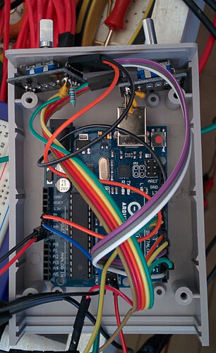
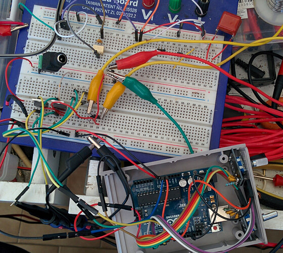
As you can see on the attached images, the whole circuit is a bit rude, but it works as planned.

The discrete component's part still requires some tuning and there is still the need to implement a decent MOSFET's driver but this is another story and it's out of the scope of this thread.

If you see something inadequate in what I've written inside the code or if you think that I could meet some unexpected behavior, feel free to note it to me.

Many thanks to all of you!

Fabrizio

Good work! Better not let that resistor on the encoder board hit the USB socket or sparks might fly!

Wow Nick, did you notice that very tiny particular?

Not only you've seen the proximity of the resistor to the USB's socket, but you've immediately understood that the resistor is on the 5V rail... impressive! (Did you, perhaps, read the wiring instruction inside the code? Tell me the truth... :wink: )

I would like to ensure that the whole circuit still need to be fixed on the plastic box and the two encoders have to be tighten with their proper bolts.

In any case, I don't think that the Arduino's board power can generate so many sparks... :grinning:

I sense the xy problem here.

MarkT:
I sense the xy problem here.

Sorry MarkT, what are you talking about?

The "xy" seem to be a pair of Cartesian coordinates...

www.xyproblem.info

MorganS:
www.xyproblem.info

@MarkT: Ok, got it (thank you MorganS). I've read with lot of accuracy the XY Problem but I'm unable to find any relation between the XY Problem itself and the current thread.

I've asked for an advice and I got the perfect solution for my problem: I was perfectly aware about my needs and I tried to explain as precisely as I could what I was looking for, enriching my request with all the details I had.

In the answers and in the sample the kind guys gave me, I've found exactly what I desired so, why did you sense this elusive xy problem?

Furthermore, having never positively contributed to the thread with any post of yours, why - once closed - did you start participating with a so useless post?

Sorry if I said that so, please, don't get offended: I think that a fantastic forum like this, with plenty of special people, deserves better and useful interventions, with the scope to help and enlighten the people involved in any kind of research.

1 Like