i am going to give input to arduino on analog pin A(0).
please see picture and read my post.
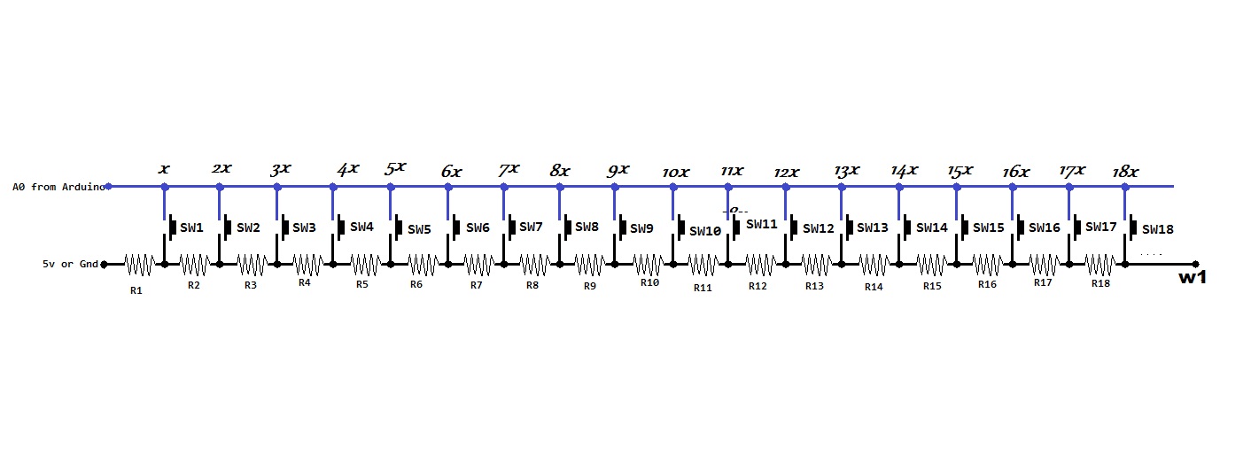
i want to make this type input switch circuit using only 3 pins A(0),5v,gnd.
i want to ask you value of resistors (R1 -to -R18) for use in circuit to get following output.
from my circuit i want......
if i press sw1 .. analogRead(0) should be equal to (suppose x).
if i press sw2 .. analogRead(0) should be equal to double of x mean 2x.
if i press sw3 .. analogRead(0) should be equal to 3 times of x mean 3x.
if i press sw4 .. analogRead(0) should be equal to 4 times of x mean 4x.
if i press sw5 .. analogRead(0) should be equal to 5 times of x mean 5x.
..........................................................
.............................................................
............................................................
if i press sw18 .. analogRead(0) should be equal to 18 times of x mean 18x.
x can be any value different from (Free_value)
here..(Free_value) is analog Reading from A(0) . when A(0) is not connected to 5v or Gnd. Means sw1 to sw18 are not pressed.
and now output from sw1 to sw18 should be less than (Free_value).
i see Free_value is not stayable. it is jumping between(300-600),
i want to get total 18 values as you read above and see in picture.and value x to 18x should be less than (Free_value).
for this type circuit .. what value of resistor R1 to R18 should be used.??????
Know that the 5 volt needs to be precise and stable. USB 5 volt, board 5 volt are not very precise.
This makes the variation in A0 readings get close to the difference between the button ladder.
Using controller 5 volt, lower the number of buttons.
Using precision 5 volt to the ladder and a precision Vref for the controller more buttons would surely be safely detected.
as long as you only want to detect one button you can use the same value for all R. W1 should go to +Vcc, W1 to GND.
Can I try any value same for all resistors????
Can I connect left side to 5v and right side to gnd,???
Without any buttons pressed, you will have a floating input. So your design will not work.
In the line that goes to the analogue input, you will need a resistor to GND at the right hand side; the left hand side of R1 will be 5V in that case and the order will be reversed (SW18 will give the lowest reading).
thank you all of you for response to my post.
but i am still confused
by my poor english as i understand your suggestions
i tried this code
void setup() {
  Serial.begin(9600);}


void loop()  {
  int POT1 = analogRead(1);
  Serial.println(POT1);
    }
and this circuit (All Resistors are 1k)
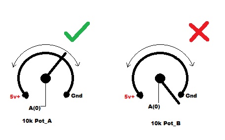
i am seeing here when no sw is pressed my A(0) is free from5v+ & Gnd ,giving jumping Reading (not Stable) in Serial Monitor,like wrong Potentiometer (Pot_B).
so My above Fig will not work .
Now i am posting an open point design below.
please write suggestion which wire should go where. which R should what value to detect each SW is pressed. it should also detect all SW are off. [ one time only one SW will be presed ]
R19 should move from the bottom of WS18 to the top of SW18.
R1 is also not needed.
w3 would be analogue input of the Arduino
w2 would be 5V
w4 would be GND
w1 is not needed
Something like below
Thank you sterretje,
I tried your circuit in post # 8
But your design also not work fully. Many SWs are giving same readings. They can't be detect different SW. I want to get 18different readings.19th when all SWs are off.
I will have to think more at it.
If you use equal resistors (e.g. 1k) for everything, the difference in reading between the switch at the right of R18 being pressed and the switch at the left of R18 will be too small to reliably detect.
For the switch at the right of R18
5V * R19 / (R19 + sum(R2..R18)) = 277 mV; analogRead() approx 57.
For the switch at the left of R18
5V * R19 / (R19 + sum(R2..R17)) = 294 mV; analogRead() approx 60.
You will have to calculate your resistors so the steps are basically evenly spaced (roughly 50). I think that the sum of the resistors has a limit of 10 kOhm.
Sorry I couldn't understand your calculation,
Parhap, I will have to follow this tutorial,
Multi buttons on Analog pin
The tutorial in the link lets ou detect multiple simultanouse button presses, but it has the tendency to not work so great due to noise on the lines - that is, for UNO and more than 4 buttons.