OK but how are you judging if it works? You can't just feed that output into an Arduino you know.
![]() why not...?
why not...?
i just connected everything by original circuit with PNP
OK but how are you judging if it works? You can't just feed that output into an Arduino you know.
![]() why not...?
why not...?
i just connected everything by original circuit with PNP
i just connected everything by original circuit with PNP
Too many links to see what comes after this amplifier.
If you are feeding it into an aruino you need a bias circuit, two resistors from analogue input to both rails. You ground now becomes the +ve of your battery.
amm...sorry but i didnt understand you....
i'm staying with this circuit:

should i added 2 resistors? where? how many ohms...?
thanx
Exactly although I would make the coupling cap (REQUIRED) from mic to base 1uF (the circuit works best with one bias source for the transistor) and the microphone WILL re-bias the transistor W/O the capacitor causing it to not work very well... As was pointed out by the "Hat mechanic" the collector to GND voltage should be very close to Vcc/2, The bias resistor for the Electret (it contains a Jfet "impedance converter to go from the Very high resistance of the Electret element to the real world) is correct in value. a 470K pot will help determine the correct base collector resistor since that exact value is dependent on the transistor Beta... without the capacitor the 10 K bias resistor causes a normal transistor to conduct hard enough to saturate... Not something an amplifier should do.
Hi beta high value resistor, lower Beta somewhat lower value of resistor.
Doc
If you are feeding it into an aruino you need a bias circuit, two resistors from analogue input to both rails.
For example the biasing :
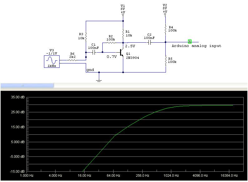
PS: capacitors - the C1 and C2 limit the low frequency characteristics of the amplifier chain. The bigger the capacitors (ie 1uF-10uF), the lower frequencies the amplifier will pass through. With 100nF the amplifier will pass rather higher frequencies (ie from 1kHz-10Khz up). With 10uF it will pass for example from 10Hz-10kHz. See below the frequency characteristics for 100nF and 10uF, for example.
I am using the resistor values from your schematics in the simulation below, but - as has been said few times in this topic - you have to set the transistors' operating point such the collector/ground is 2.5V - with this "optimal" setting this amplifier has about 40dB gain in the passband.
Note to hi-fi purists - this frequency analysis does not use the AC generator voltages as depicted on the pictures below :.

i appreciate the schematics very much, but i only have left:
resistors - 1 of 100K (and 1 is already connected to circuit), and 2 resistors of 47K
capacitors - 0.1uF, 10uF, 33uF, 47uF, 22pF
i gusse it's not enough right?
so i'll make a quick delivery, should i get the componnents of your last circuit (pito), or just order a normal NPN, use the original circuit and connect straight to arduino? will it work?
All circuits need those two resistors to connect to the arduino analogue input.
All circuits need those two resistors to connect to the arduino analogue input.
what about the original one? you have only capacitor of 0.2 before Output (arduino input)
Instead of 2x 100k for biasing you may use 2x 47k too.
For proper transistor's working point setting order few resistors from ie 100k, 120k,150k,180k, 220k, 270k, 330k, 390k or use a pot. trimmer.
You may experiment with any capacitors you have there, except 22pF one (too small for audio).
ok, so i've connected everything like here:
with these changes:
in the Serial Monitor i'm getting the same results as before - a range of 698-702~
this is the transistor: ss8550 to-92 (i looked at the datasheet - seems ok to me)
i'm using the Arduino 3v, because the 5v gives me 1023 (saturated?)
and this is the code:
void setup(){

Serial.begin(9600);
}
void loop(){
  int mic = analogRead(0);
Serial.println(mic);
delay(65);
}
Have a look at the voltage values, I do assume your Vcc is now 3.37V.
Vcollector=Vemitter=3.37V=Vcc
It seems to me the transistor is fully open, as the base-collector resistor is too small. When the gain of your transistor is large (it could be up to 400), you need much smaller base current to set the collector voltage to Vcc/2. In order to get the transistor half-open (vcc/2), you have to increase the base-collector resistor. I do not know how much as it fully depends on the transistor you have got. I would assume 250k - 350k could be the range.
As we said: unless Vcollector will not be aprox.=Vcc/2, the amplifier will not amplify.. ![]()
because the 5v gives me 1023 (saturated?)
You cannot read 1023 when using those biasing resistors (2x47k). So you may have an wiring problem somewhere.
The capacitor C2 isolates DC from the transistor, so you must read something like 510-512 (because the biasing resistors create that Vcc/2 at the analog input - there is where its name comes from: "to bias"). The biasing is there to get the signal values symmetrical around 511. When you start talk into the MIC, you will get +/- 10mV (peak) signal from the MIC, after the amplification you will get +/- 1V peak, symmetrical around Vcc/2. So the values (peak) you will read with ADC will span 1.5V-3.5V at the analog input (because the mid is biased to 2.5V). Perfect. Then you may sample it with 10ksamples/sec, do FFT, you get spectra, and do your analysis as you want.. :0
Check the 47k resistor values.
As the first step try to fix the analog input bias - you must read 512 (+/-2) stable.
And i'm using PNP transistor
So you have not got that circuit or at least you should not have that circuit.
Please draw what you have not something that you then have to have a list of amendments.
How would you feel reading a story about a mad fighting a bear and finding a note at the end saying that the main protagonist was actually a woman and no combat took place, but they thought about it a lot.
so this is the transistior i'm using: pnp transistor ss8550 to-92
i also have this pot: B50K ---but im not sure about a datasheet
Check the 47k resistor values
i checked on the multimeter - it's correct.
o you have not got that circuit or at least you should not have that circuit.
ok, i didnt' mention that i connected the Mic the opposite way then the schematic (mic's Gnd leg connected r3+c1) like we agreed before.
weird thing - so i'm not sure how should i connect the transistor, and i switch it sometime to check bot option. in one of the times i switched it i forgot to unplugged the usb cable (which feeds the arduino), and i got the same values even when the transistor wasn't even connected !
weird thing - so i'm not sure how should i connect the transistor
That is because we have shown too many pictures to you..
That is because we have shown too many pictures to you
no..it's not because of that, it's that that i'm not sure what do u call Emmiter and what collector ( but i know how to activate the PNP with simple led.
Anyway - any idea for how should continue trouble shooting...?
The emitter is the one with the arrow on it.
The position of the transistor's leg with the emitter on it is given in the data sheet for the transistor.
Hints :- draw exactly what you plan to make and post it.
Hints :- draw exactly what you plan to make and post it.
ok, ive connected everything like in the schematic ahead, with TWO major changes:
thank you
There are three major changes needed if you follow GMs advice.
Look what the hell is wrong with you?
Why will you not draw what you are going to make.
No that circuit is not right even with that list. You have been told many times but you just ignore us.
I don't beleve that electronics is the hobby for you.
If you are not capable of drawing it you are not capable of making it.
what do u mean drawing it??
whats wrong with telling u what circuit i made??
what do u need to know? what do you wanna find out from the "drawing"?