Using Arduino nano, I want to measure the AC voltage of -0.5V to 0.5V. To do that, I want to change the -0.5V~0.5V input voltage to 0V~5V output voltage using op amp and measure it in Arduino, how should I configure the circuit?
cf. I'm using op275.

At first, I designed circuit like this but it can not measure negative voltage.
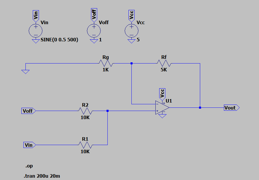
The easiest way to do this with an op-amp is to use a summing amplifier with a Voffset to bias the signal into the positive range. An example circuit is shown below:
If you used a Voffset of 0.5V your input signal would be 0-0.5V centered on 0.25V. However most op-amps can't get quite to 0V on a single supply. Using a 1V offset results in a signal from 0.25V to 0.75V centered on 0.5V. So -0.5V in = 0.25V, +0.5V in = 0.75V. With an amplifier gain of 6 as shown your input 0f -0.5V..0.5V is now +1.5V to +4.5V centered on +3V.
That is a workable range however the op-amp you reference is not rail to rail and it will saturate before you get to 4.5V with a 5V Vcc. You might have to cut the gain to 4 to prevent the op-amp from saturating at +0.5V input. I would choose a different op-amp personally.
Also you have not told us anything about your source, it's frequency, impedance etc or what you are trying to do. The circuit shown works on paper but there are many other factors and potential problems with a real circuits performance.