I'm currently setting up a project that utilizes two Powerswitch Tail II relays. My goal is to alternate the two of them so one is off and the other is on every 15 seconds, but I've run into the issue of the breadboard. I realize I could (probably) directly connect the powerswitch tails to the arduino itself but I'd like to understand the breadboard more. That and the cables I have available are too short and the Powerswitch Tails too big. I'd like the extra room.
I'm a bit lost on the logic of the breadboard wiring and was wondering if anyone had any insights on how one would properly wire the breadboard. Perhaps even the wiring in general. What happens when Arduino uses digitalWrite(pin, HIGH/LOW);? Does it send data through one of the wires, or switch certain wires on or off?
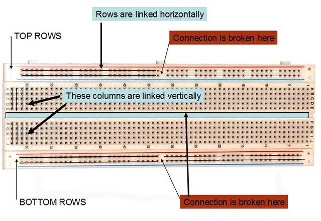
What I understand so far is that the rows of numbers have 5 available connected connections (A1,B1,C1,D1,E1) and are separated by the ravine and different # rows . So too that I could use the X & Y rows (Buses/Rails) to provide Power/Grounding to those columns.
Code below
/**
 * This project will be utilizing two Powertail Switch II relays to control fans.
 * The fans, pointed in opposite directions and taped together will control airflow
 * between two mostly closed off locations, acheiving the desired visual effect of
 * "breathing" as desired by the artist.
 *
 * The fans must therefore alternate between on and off states through having the
 * two Powertailswitch II relays alternate between on and off states
 *
 * B = Bottom
 * T = Top
 * PT = Powertail
 */
int pinOutTPT = 8;
int pinOutBPT = 9;

void setup(){
  Serial.begin(9600);
  pinMode(8, OUTPUT);
  pinMode(9, OUTPUT);
}
  //Begin with TPT running alone for 15 seconds with BPT fan off
  digitalWrite(pinOutTPT, HIGH);
  digitalWrite(pinOutBPT, LOW);

  //Run top fan for 4 seconds
  delay(4000);

  //Alternate fans, making TPT turn off and BPT turn on
  digitalWrite(pinOutTPT, LOW);
  digitalWrite(pinOutBPT, HIGH);

  //Run bottom fan for 4 seconds
  delay(4000);
}
Center of breadboard is columns ( a column is vertical) of 4 or more holes that share the same metal clip inside that column. The outside is the power bus rail rows (a row is horizontal) Power bus rails typically run from the left side all the way across to the right side. Some longer breadboards are not connected in the middle so it's necessary to add jumpers to connect the left half with the right half. Components are conducted by sharing a column or by jumpers. Red is positive rail. Blue at the top rail is GND rail . Blue at the bottom rail can be negative rail if there is one. Any component that has leads small enough to fit in a hole can be plugged into the breadboard. Components with larger leads must be soldered to 20 gusge solid copper hookup wire which is then plugged into board. No wires that carry more than 5 A should be plugged into board. That's all you need to know. Use a multimeter to check continuity if you have any doubts.
(blue wire is 20 guage AWG SOLID COPPER. white wire is 22 guage AWG S:TRANDED. Blue wires are SOLDERED to white wires. Blue wires plug into breadboard for perfect fit, white wires are long and flexible)
If it makes you feel better the white wires have small paper labels on each wire.
What is the logic behind the broken connections of the power rails?
For split supplies, i.e. +-15V etc.
Also, +5V on TOP LEFT SIDE, +12V on TOP RIGHT SIDE, and the split supplies i.e. +-15V etc on the BOTTOM LEFT and BOTTOM RIGHT.
I have one of these and there IS a break in the center. LOOK CLOSELY at the spacing in the center compared to the spacing between the other groups on the power rails. Note that this breadboard has no blue & red color bars and also is dull white as opposed to the shiny white color of the ones that have the blue and red lines, like the ones you have.
@OP,
Your jumpers from the Power Switch tail are too short. You need MALE to FEMALE jumpers to EXTEND them (put as many as necessary to extend lenght from Power Switch Tail to breadboard.
When quoting the guage of a wire please state which standard you are refering to - AWG, SWG or something
else. Or better still just state the diameter, easier to understand all round!
I think those side rails are only broken if the blue and red lines are broken.
Tom...
I have both kinds - connected the entire length, and split. the red and blue lines are solid or split as are the conductors. Working with Arduino, I much prefer the unsplit/connected style. On the occasions where I've used two voltages (like with a motor), I prefer to use the top and bottom set. A single wire to connect the grounds goes from one edge to the other.
I have found that the quality of breadboards varies. Some of them quit working reliably after only a few insertions, while others function flawlessly for years. My guess is the metal used for the contacts makes this difference.