I have been encountering a problem with powering my environmental system prototype.
To give you an overview of my system, I am using an Arduino UNO, a DC Mini Submersible Water Pump (with a voltage range of 3V to 6V), a wifi esp8266 module (which requires 3.3V) and other air/water sensors.
The Arduino UNO is powered through the USB interface.
w the external power supply is connected, the wifi module stops working, and I suspect this is due to voltage and current issues. Initially, the system worked smoothly, connecting to the wifi, operating the pump, taking readings from the air/water sensors, and sending them to the cloud before waiting for ten minutes and repeating the process. However, after the initial run, the wifi module refuses to connect.
It appears that combining these two components is causing a lot of issues. The system either works with the water pump only or the wifi module. I believe that there may be a problem with the voltage or current that is causing this issue.
I really appreciate any help, support and sight I have been struggling with this for weeks.
First of all your transistor circuit is inapplicable. Move the load and diode between + and collector. Even then the TIP transistors drop too much voltage, use a logic level MOSFET instead.
You do absolutely need level conversion. If you don't use it you could end up destroying your ESP01. In response to your question, read these two links which I got from @alto777:
Take your pick. I like using a voltage dividers and relying on the logic level thresholds.
Just don't put 5 volts out to an input on the 3.3 volt parts.
Arduino UNO is great for beginners, but if power consumption is not a big worry in your project, and all your inputs are a 3.3v operating level, then using an ESP32 dev board would give you way more processing power and memory, along with built in WiFi and around 30 GPIO pins. A cheaper option would be the ESP8266
The Atlas pH sensor and interface board is best read with Serial. The UNO is less than optimal because you will have to use software serial which is not at robust at hardware serial.
I have used the Atlas pH probe with a Nano Every which has a second hardware serial port independent from the usb serial.
The data sheet indicates that they will run with 3.3 - 5.5v Vcc, and the pH probe should work fine with an ESP32 which has a several hardware serial ports independent from usb.
Given your need for WiFi in the project, I would be advising trying to make all the components work with the ESP32.
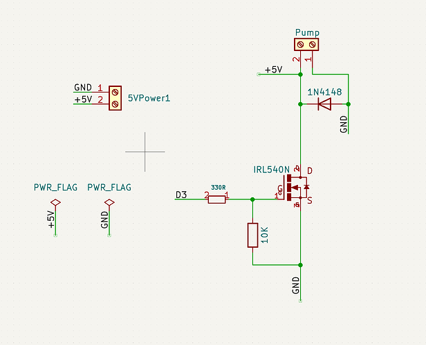
Thanks to everyone who helped me in understanding the concept of logic level MOSFET. I spent an entire day studying various tutorials to grasp the main concept, but I am still a bit confused about which diode would be suitable for my system and the correct wiring.
I have summarized the specifications of the component and created an initial schematic, but it may not be entirely correct.
I would be grateful if any of you guys could provide me with advice.
The Water Submersible Pump:
Powered by 3 - 6V voltage
Current: 130 - 220 mA
External Power Supply:
Powered by 3 - 6V voltage (I’m selecting 5V)
It can supply with any current less than 2A
Logic-level MOSFET:
IRL540N, Its gate threshold voltage (VGS) ranges from 1 to 2 volts.
IRL540N has a low on-resistance (RDS(on)) of 0.077 ohms.